SOFTWARE OVERVIEW
The Modbus Command column shows the Modbus command assigned by the wizard. The Modbus command is automatically selected by the wizard based on the selected address and direction.
CONNECTING DEVICES The fourth step in the configuration wizard connects one or more devices to the sub- network. Devices on a
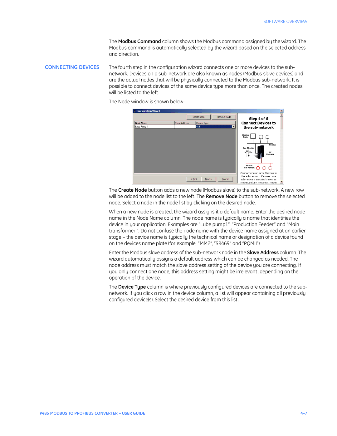
The Node window is shown below:
The Create Node button adds a new node (Modbus slave) to the
When a new node is created, the wizard assigns it a default name. Enter the desired node name in the Node Name column. The node name is typically a name that identifies the device in your application. Examples are “Lube pump1”, “Production Feeder” and “Main transformer “. Do not confuse the node name with the device name assigned at an earlier stage – the device name is typically the technical name or designation of a device found on the devices name plate (for example, “MM2”, “SR469” and “PQMII”).
Enter the Modbus slave address of the
The Device Type column is where previously configured devices are connected to the sub- network. If you click a row in the device column, a list will appear containing all previously configured device(s). Select the desired device from this list.
P485 MODBUS TO PROFIBUS CONVERTER – USER GUIDE |
