COMMUNICATION MODEL
The P485 uses
It is still possible, though, to define custom message frames by creating a transaction instead of selecting a
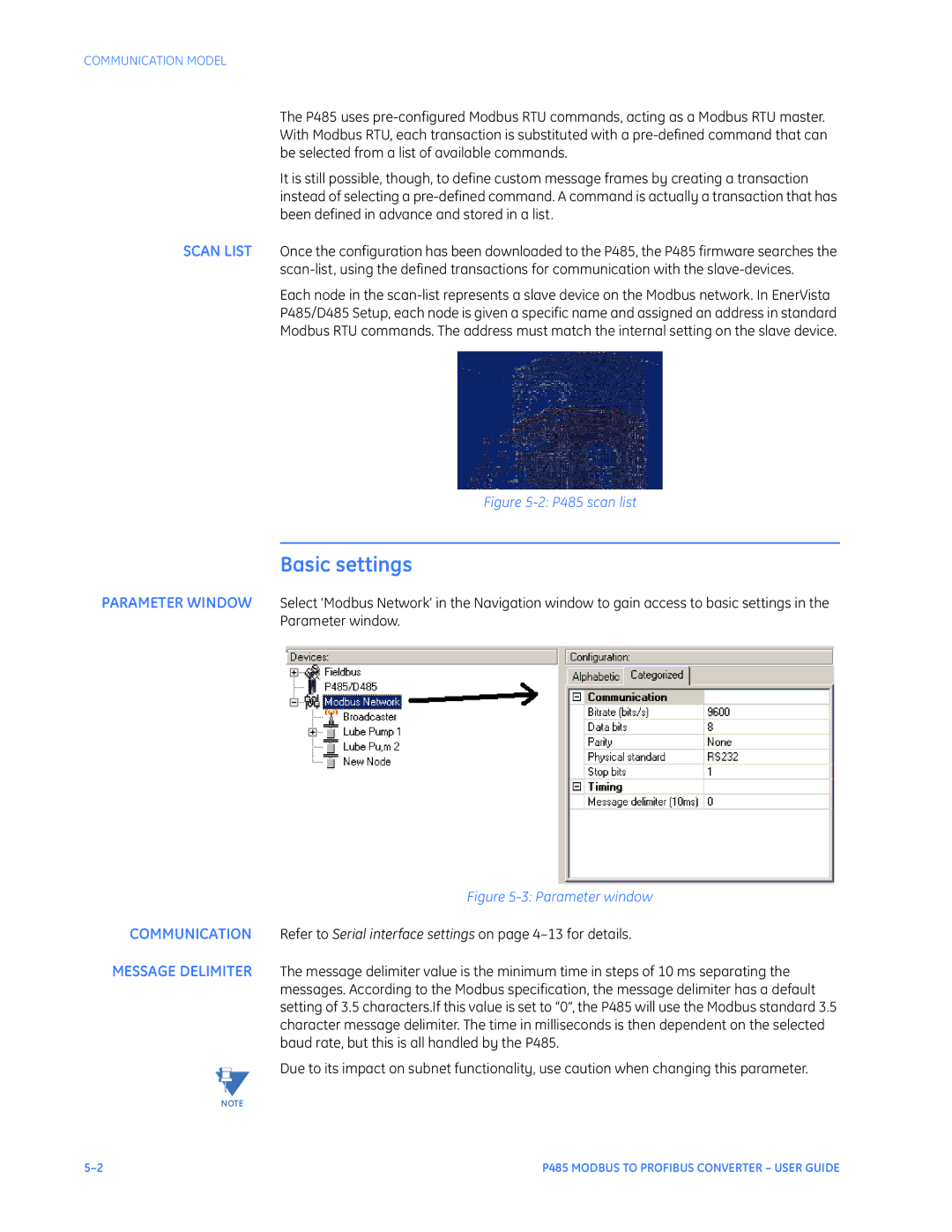
SCAN LIST Once the configuration has been downloaded to the P485, the P485 firmware searches the
Each node in the
P485/D485 Setup, each node is given a specific name and assigned an address in standard
Modbus RTU commands. The address must match the internal setting on the slave device.
Figure 5-2: P485 scan list
Basic settings
PARAMETER WINDOW Select ‘Modbus Network’ in the Navigation window to gain access to basic settings in the Parameter window.
Figure 5-3: Parameter window
COMMUNICATION Refer to Serial interface settings on page
MESSAGE DELIMITER The message delimiter value is the minimum time in steps of 10 ms separating the messages. According to the Modbus specification, the message delimiter has a default setting of 3.5 characters.If this value is set to “0”, the P485 will use the Modbus standard 3.5 character message delimiter. The time in milliseconds is then dependent on the selected baud rate, but this is all handled by the P485.
Due to its impact on subnet functionality, use caution when changing this parameter.
NOTE
P485 MODBUS TO PROFIBUS CONVERTER – USER GUIDE |