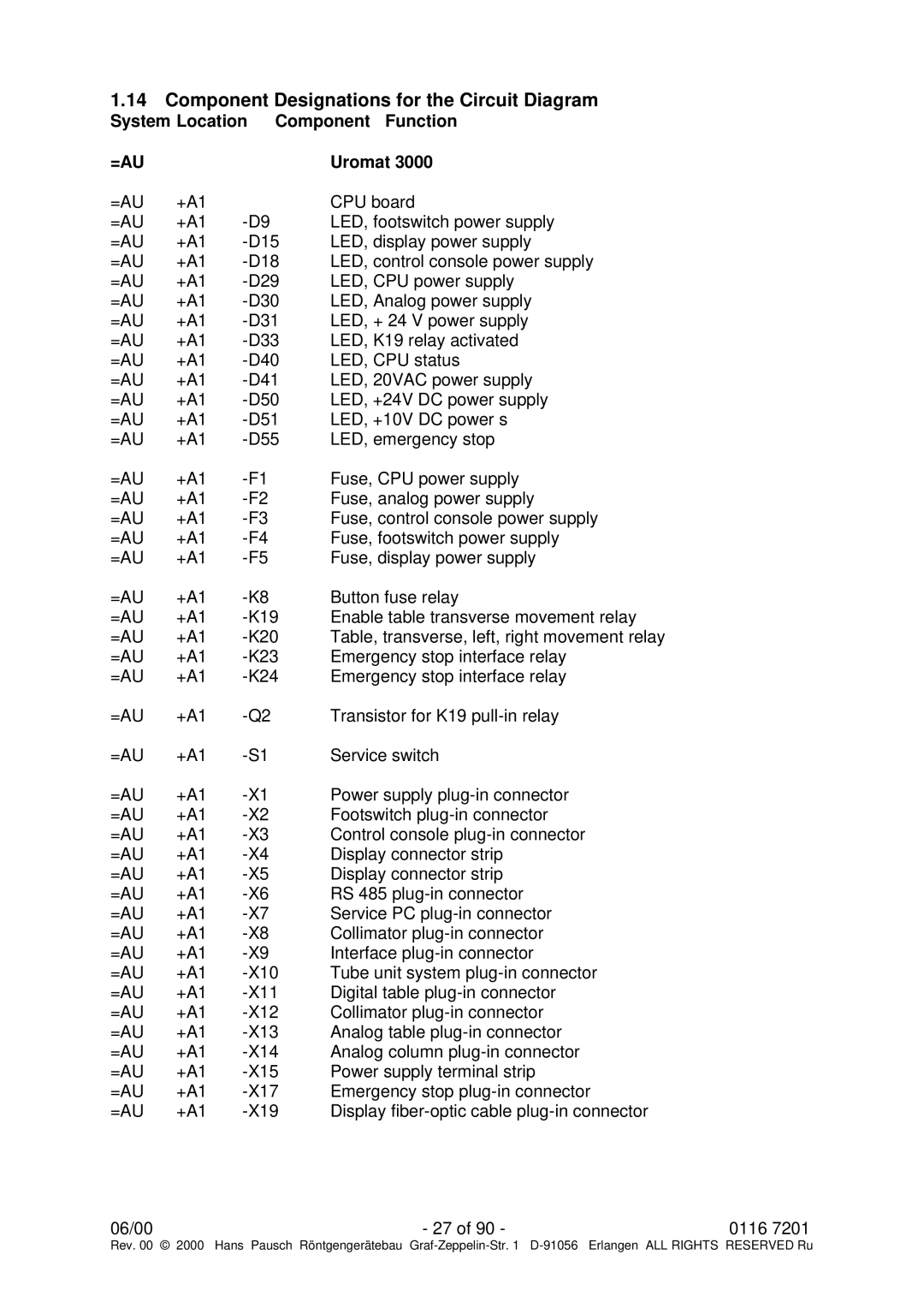
1.14 Component Designations for the Circuit Diagram
System Location Component Function
=AU |
|
| Uromat 3000 |
=AU | +A1 |
| CPU board |
=AU | +A1 | LED, footswitch power supply | |
=AU | +A1 | LED, display power supply | |
=AU | +A1 | LED, control console power supply | |
=AU | +A1 | LED, CPU power supply | |
=AU | +A1 | LED, Analog power supply | |
=AU | +A1 | LED, + 24 V power supply | |
=AU | +A1 | LED, K19 relay activated | |
=AU | +A1 | LED, CPU status | |
=AU | +A1 | LED, 20VAC power supply | |
=AU | +A1 | LED, +24V DC power supply | |
=AU | +A1 | LED, +10V DC power s | |
=AU | +A1 | LED, emergency stop | |
=AU | +A1 | Fuse, CPU power supply | |
=AU | +A1 | Fuse, analog power supply | |
=AU | +A1 | Fuse, control console power supply | |
=AU | +A1 | Fuse, footswitch power supply | |
=AU | +A1 | Fuse, display power supply | |
=AU | +A1 | Button fuse relay | |
=AU | +A1 | Enable table transverse movement relay | |
=AU | +A1 | Table, transverse, left, right movement relay | |
=AU | +A1 | Emergency stop interface relay | |
=AU | +A1 | Emergency stop interface relay | |
=AU | +A1 | Transistor for K19 | |
=AU | +A1 | Service switch | |
=AU | +A1 | Power supply | |
=AU | +A1 | Footswitch | |
=AU | +A1 | Control console | |
=AU | +A1 | Display connector strip | |
=AU | +A1 | Display connector strip | |
=AU | +A1 | RS 485 | |
=AU | +A1 | Service PC | |
=AU | +A1 | Collimator | |
=AU | +A1 | Interface | |
=AU | +A1 | Tube unit system | |
=AU | +A1 | Digital table | |
=AU | +A1 | Collimator | |
=AU | +A1 | Analog table | |
=AU | +A1 | Analog column | |
=AU | +A1 | Power supply terminal strip | |
=AU | +A1 | Emergency stop | |
=AU | +A1 | Display |
06/00 | - 27 of 90 - | 0116 7201 |
Rev. 00 © 2000 Hans Pausch Röntgengerätebau Graf