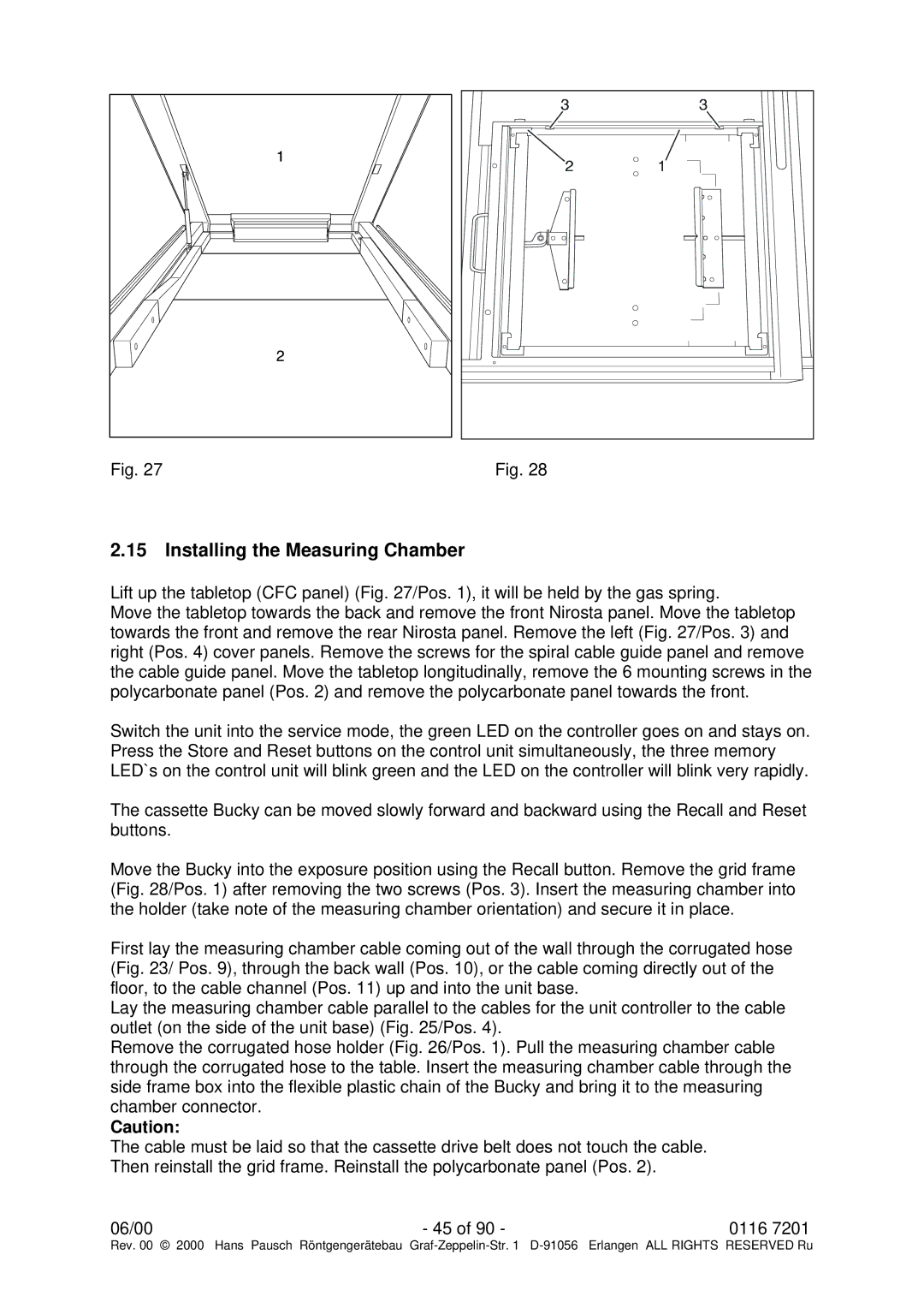
Fig. 27 | Fig. 28 |
2.15 Installing the Measuring Chamber
Lift up the tabletop (CFC panel) (Fig. 27/Pos. 1), it will be held by the gas spring.
Move the tabletop towards the back and remove the front Nirosta panel. Move the tabletop towards the front and remove the rear Nirosta panel. Remove the left (Fig. 27/Pos. 3) and right (Pos. 4) cover panels. Remove the screws for the spiral cable guide panel and remove the cable guide panel. Move the tabletop longitudinally, remove the 6 mounting screws in the polycarbonate panel (Pos. 2) and remove the polycarbonate panel towards the front.
Switch the unit into the service mode, the green LED on the controller goes on and stays on. Press the Store and Reset buttons on the control unit simultaneously, the three memory LED`s on the control unit will blink green and the LED on the controller will blink very rapidly.
The cassette Bucky can be moved slowly forward and backward using the Recall and Reset buttons.
Move the Bucky into the exposure position using the Recall button. Remove the grid frame (Fig. 28/Pos. 1) after removing the two screws (Pos. 3). Insert the measuring chamber into the holder (take note of the measuring chamber orientation) and secure it in place.
First lay the measuring chamber cable coming out of the wall through the corrugated hose (Fig. 23/ Pos. 9), through the back wall (Pos. 10), or the cable coming directly out of the floor, to the cable channel (Pos. 11) up and into the unit base.
Lay the measuring chamber cable parallel to the cables for the unit controller to the cable outlet (on the side of the unit base) (Fig. 25/Pos. 4).
Remove the corrugated hose holder (Fig. 26/Pos. 1). Pull the measuring chamber cable through the corrugated hose to the table. Insert the measuring chamber cable through the side frame box into the flexible plastic chain of the Bucky and bring it to the measuring chamber connector.
Caution:
The cable must be laid so that the cassette drive belt does not touch the cable. Then reinstall the grid frame. Reinstall the polycarbonate panel (Pos. 2).
06/00 | - 45 of 90 - | 0116 7201 |
Rev. 00 © 2000 | Hans Pausch Röntgengerätebau Graf |