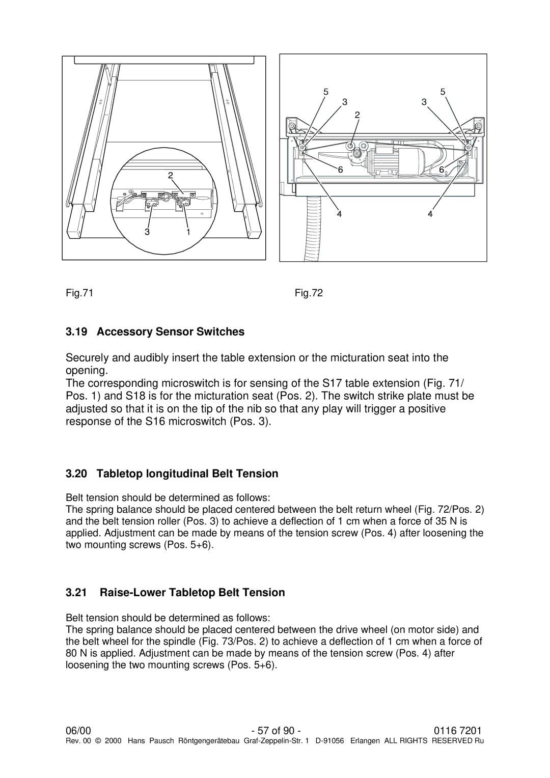
Fig.71 |
Fig.72 |
3.19 Accessory Sensor Switches
Securely and audibly insert the table extension or the micturation seat into the opening.
The corresponding microswitch is for sensing of the S17 table extension (Fig. 71/ Pos. 1) and S18 is for the micturation seat (Pos. 2). The switch strike plate must be adjusted so that it is on the tip of the nib so that any play will trigger a positive response of the S16 microswitch (Pos. 3).
3.20 Tabletop longitudinal Belt Tension
Belt tension should be determined as follows:
The spring balance should be placed centered between the belt return wheel (Fig. 72/Pos. 2) and the belt tension roller (Pos. 3) to achieve a deflection of 1 cm when a force of 35 N is applied. Adjustment can be made by means of the tension screw (Pos. 4) after loosening the two mounting screws (Pos. 5+6).
3.21Raise-Lower Tabletop Belt Tension
Belt tension should be determined as follows:
The spring balance should be placed centered between the drive wheel (on motor side) and the belt wheel for the spindle (Fig. 73/Pos. 2) to achieve a deflection of 1 cm when a force of 80 N is applied. Adjustment can be made by means of the tension screw (Pos. 4) after loosening the two mounting screws (Pos. 5+6).
06/00 | - 57 of 90 - | 0116 7201 |
Rev. 00 © 2000 | Hans Pausch Röntgengerätebau Graf |