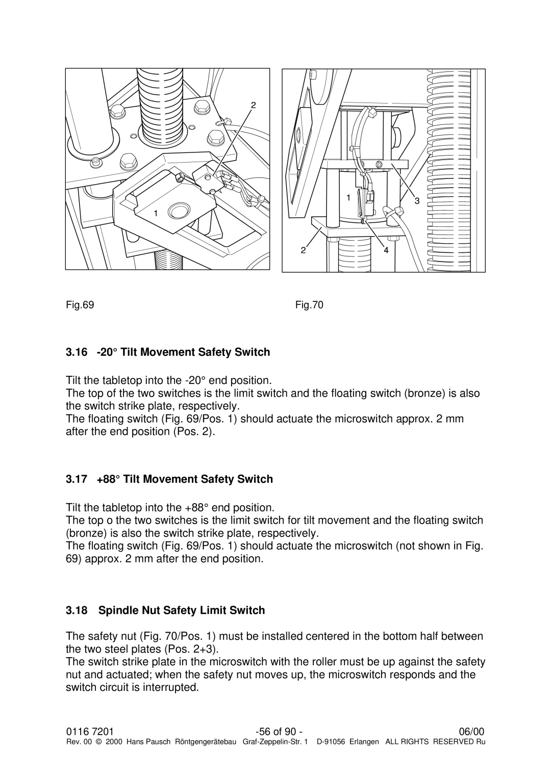
Fig.69 |
Fig.70 |
3.16 -20° Tilt Movement Safety Switch
Tilt the tabletop into the
The top of the two switches is the limit switch and the floating switch (bronze) is also the switch strike plate, respectively.
The floating switch (Fig. 69/Pos. 1) should actuate the microswitch approx. 2 mm after the end position (Pos. 2).
3.17 +88° Tilt Movement Safety Switch
Tilt the tabletop into the +88° end position.
The top o the two switches is the limit switch for tilt movement and the floating switch (bronze) is also the switch strike plate, respectively.
The floating switch (Fig. 69/Pos. 1) should actuate the microswitch (not shown in Fig. 69) approx. 2 mm after the end position.
3.18 Spindle Nut Safety Limit Switch
The safety nut (Fig. 70/Pos. 1) must be installed centered in the bottom half between the two steel plates (Pos. 2+3).
The switch strike plate in the microswitch with the roller must be up against the safety nut and actuated; when the safety nut moves up, the microswitch responds and the switch circuit is interrupted.
0116 7201 | 06/00 | |
Rev. 00 © 2000 Hans Pausch Röntgengerätebau | Graf |