Installation Instructions Uromat
Contents
Technical Maintenance
Adjustments
Not configured
Component Dimensions
General Safety Information
Component Weights
Packaging Dimensions and Weights
Component Designations
Dimensional Drawing, Right-handed Version
FFA
Dimensional Drawing, Left-handed Version
FFA
345 Drehachse
Dimensional Drawing for Floor Mounting, Left-handed Version
0116 06/00
Required Test Equipment
Power Line Connection Data
Required Special Tools
Conditions for Transport and Storage
Circuit Diagram,
Contents of Circuit Diagram
06/00 0116
Circuit Diagram,
Circuit Diagram,
Circuit Diagram,
Circuit Diagram,
Circuit Diagram,
Circuit Diagram,
Circuit Diagram,
Circuit Diagram,
Circuit Diagram,
Circuit Diagram,
Circuit Diagram,
Circuit Diagram,
Collimator connection
System Location Component Function
Component Designations for the Circuit Diagram
Uromat
LED1
+A6 Terminal strip for Bucky
Cassette box motor potentiometer
Function Description of the Controller
Boards
CPU Board
Breaker Board
Footswitch Board Control Unit
Display Board
Preparations for Mounting
Unpacking the Unit
Removing the Unit from the Pallet
Installing the Unit Column
Aligning the Unit Column
Temporarily Connecting Line Power
Installing the Tube Unit Support Arm
Preinstalling the Tube Unit Collimator Combination
Installing the Image Intensifier
Laying the Collimator Cables
Laying the High Voltage Cables
To lay cables in the unit, 7 meters are required
Page
Making the Power Connection through the Generator
Laying the I.I. Cable
Installing the Measuring Chamber
Installing the Grid Replacing the Grid
Installing the Tilt Angle Display- Error Display
Installing the Cover Panels
Installing the Monitor Support Arm Option
Installing the Mount for the Flush Bowl
Sealing the Table Frame Cover Panel
Adjustment
Tube Unit Support Arm
Central Beam Center
Central Beam Center of Bucky
Lengthwise to the tabletop, for this
Movement Path Potentiometer, Tabletop longitudinal
Bucky Cassette Tray Movement Path Potentiometer
Movement Path Potentiometer, Tabletop transverse
I.I. Carriage System Potentiometer
Potentiometer 1 Table Tilt Movement Path
Potentiometer 2 Table Tilt Movement Path
Tabletop Longitudinal Safety Switch
Tabletop Transverse Safety Switch Not configured
Table Up Movement Path Switch Strike Plate
Bucky Movement Path Safety Switch
13 I.I. Carriage Movement Path Safety Switch
Table Down Movement Path Switch Strike Plate
17 +88 Tilt Movement Safety Switch
16 -20 Tilt Movement Safety Switch
Spindle Nut Safety Limit Switch
Tabletop longitudinal Belt Tension
Accessory Sensor Switches
Raise-Lower Tabletop Belt Tension
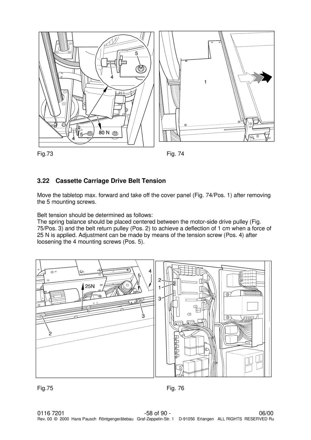
Cassette Carriage Drive Belt Tension
Operation in the Service Mode
Equipment
Setting Parameters
Procedure
Adjusting the Axes
Startup
Collimator Basic Setting
Cassette Format
Setting the Collimator to the Cassette and I.I. Format
Format
Saving the Parameters in the PC
Electronic Adjustment Parameters
Setup Parameters
Tabletop long. Store yes/no 1/0
Technical Maintenance
Mechanical and Electrical Checks
Preparations
Page
Function Check
Page
176
Spare Parts, Overview
41/43 40/41 /10
Spare Parts, Unit Column Right-handed, Left-handed Versions
122 125 11 119 120 121 151
Spare Parts, Table Frame Tabletop, Right-handed Version
128 135 185 136
Spare Parts, Table Frame Tabletop, Left-handed Version
Spare Parts, Tube Unit Support Right-handed Version 193 191
213 209 202 203 191 192 197 194 193 198 201 207 / 210
209 207 / 210
Spare Parts, Tube Unit Support Left-handed Version
Spare Parts, Accessories
249 155 156
Spare Parts List
Pos Designation
Pos Designation
Pos Designation
Pos Designation
Pos Designation
Troubleshooting
Error Cause Corrective Measure Number
Page
Board Replacement
Version Update
Maintenance Verification
Location of Identification Labels Labeling
Max kg/ 66 lb
Overview of Labels