3.25 Collimator Basic Setting
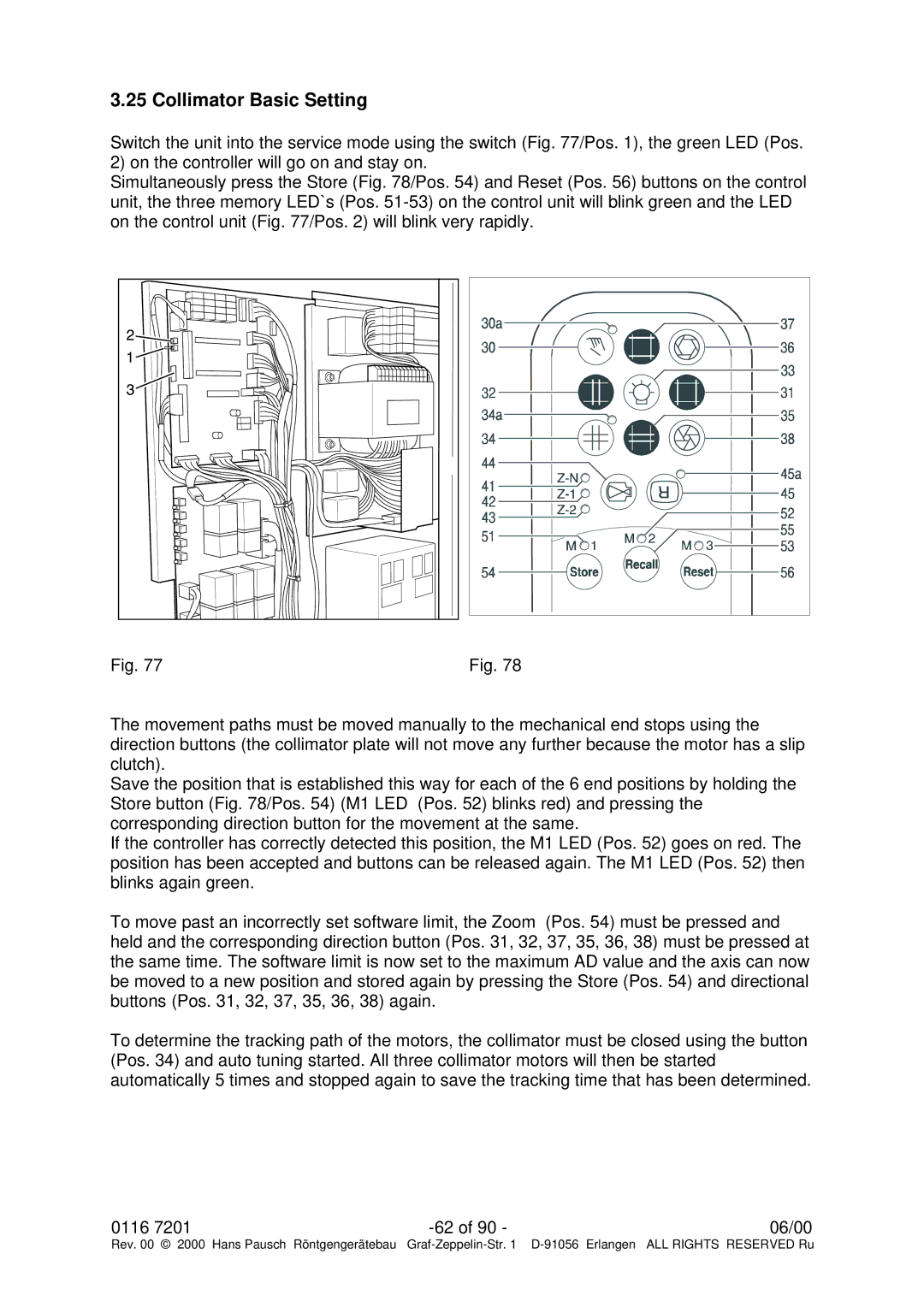
Switch the unit into the service mode using the switch (Fig. 77/Pos. 1), the green LED (Pos. 2) on the controller will go on and stay on.
Simultaneously press the Store (Fig. 78/Pos. 54) and Reset (Pos. 56) buttons on the control unit, the three memory LED`s (Pos.
Fig. 77 | Fig. 78 |
The movement paths must be moved manually to the mechanical end stops using the direction buttons (the collimator plate will not move any further because the motor has a slip clutch).
Save the position that is established this way for each of the 6 end positions by holding the Store button (Fig. 78/Pos. 54) (M1 LED (Pos. 52) blinks red) and pressing the corresponding direction button for the movement at the same.
If the controller has correctly detected this position, the M1 LED (Pos. 52) goes on red. The position has been accepted and buttons can be released again. The M1 LED (Pos. 52) then blinks again green.
To move past an incorrectly set software limit, the Zoom (Pos. 54) must be pressed and held and the corresponding direction button (Pos. 31, 32, 37, 35, 36, 38) must be pressed at the same time. The software limit is now set to the maximum AD value and the axis can now be moved to a new position and stored again by pressing the Store (Pos. 54) and directional buttons (Pos. 31, 32, 37, 35, 36, 38) again.
To determine the tracking path of the motors, the collimator must be closed using the button (Pos. 34) and auto tuning started. All three collimator motors will then be started automatically 5 times and stopped again to save the tracking time that has been determined.
0116 7201 | 06/00 |
Rev. 00 © 2000 Hans Pausch Röntgengerätebau Graf