2.6 Temporarily Connecting Line Power
Caution:
If the unit is connected to a different line power than that listed on the order, the setting must be changed to the one that corresponds to the local line power as specified by the Wiring Diagram to the power line transformer (Fig. 12/Pos. 1).
Provide the unit with power by connecting a temporary connection cable
Connect the
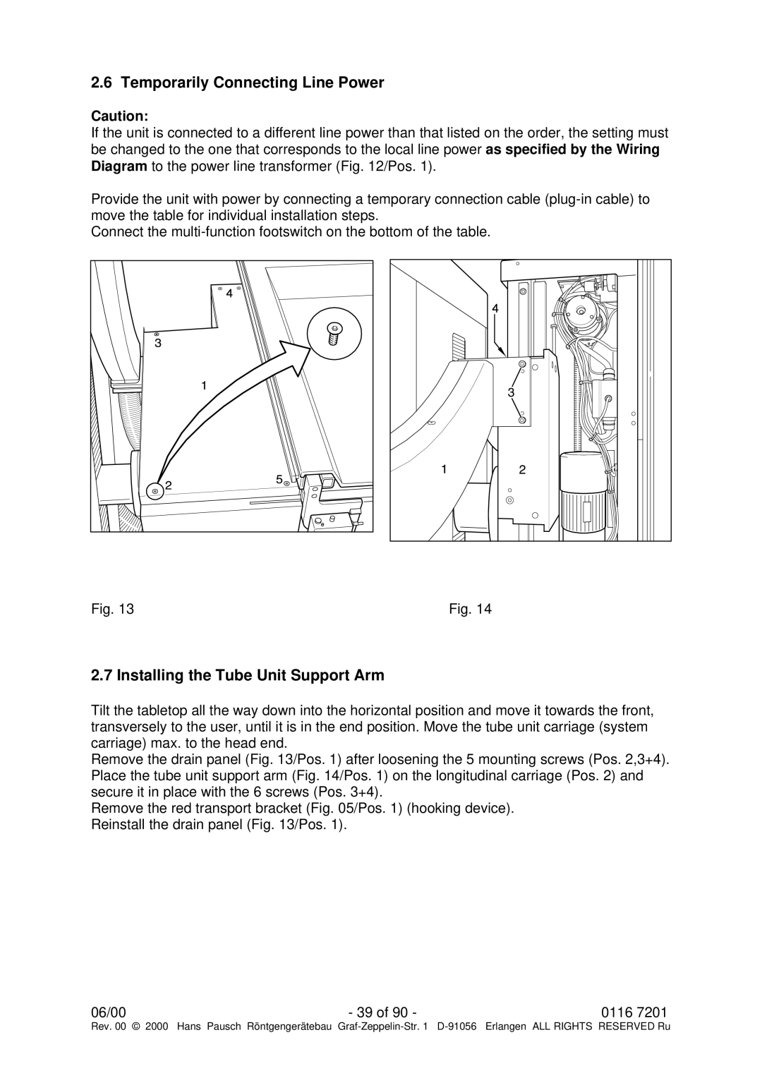
Fig. 13 | Fig. 14 |
2.7 Installing the Tube Unit Support Arm
Tilt the tabletop all the way down into the horizontal position and move it towards the front, transversely to the user, until it is in the end position. Move the tube unit carriage (system carriage) max. to the head end.
Remove the drain panel (Fig. 13/Pos. 1) after loosening the 5 mounting screws (Pos. 2,3+4). Place the tube unit support arm (Fig. 14/Pos. 1) on the longitudinal carriage (Pos. 2) and secure it in place with the 6 screws (Pos. 3+4).
Remove the red transport bracket (Fig. 05/Pos. 1) (hooking device). Reinstall the drain panel (Fig. 13/Pos. 1).
06/00 | - 39 of 90 - | 0116 7201 |
Rev. 00 © 2000 Hans Pausch Röntgengerätebau Graf