2.Installation
2.1Preparations for Mounting
Prepare the unit location according to the dimensional drawing, Page 6 or 7 or Page 8 or 9.
Caution: The minimum distances listed in the dimensional drawings must be maintained to assure that all movements of the system are possible.
The floor must be capable of bearing a load of 10,450 N on the front mounting points according to Dimensional Drawing, Pages 8 and 9.
The P2 mounting points on the back of the unit must each be capable of assuming 1020 N pull.
Example: Liebig S12/40 or S12/65 expansion bolts with an image quality of 2 with a concrete quality of B 25, DIN 1045. The minimum drill hole depth may be 80 or 105 mm.
With a vinyl tile floor, the floor covering must be cut out in the area of the unit base.
2.2Unpacking the Unit
Open the crate and remove the protective film (Fig. 01 /Pos. 1). Only open the cartons (Pos. 2,3+4) and place them to one side until it is time to use them.
Check the items included in the shipment or the parts for completeness and for good condition.
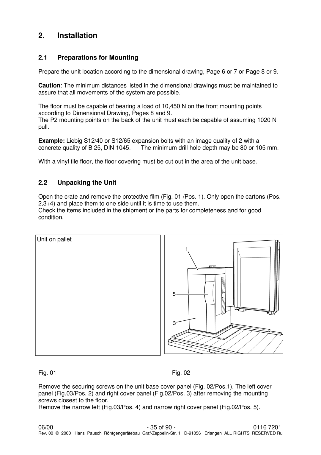
Unit on pallet
Fig. 01 | Fig. 02 |
Remove the securing screws on the unit base cover panel (Fig. 02/Pos.1). The left cover panel (Fig.03/Pos. 2) and right cover panel (Fig.02/Pos. 3) after removing the mounting screws closest to the floor.
Remove the narrow left (Fig.03/Pos. 4) and narrow right cover panel (Fig.02/Pos. 5).
06/00 | - 35 of 90 - | 0116 7201 |
Rev. 00 © 2000 Hans Pausch Röntgengerätebau Graf