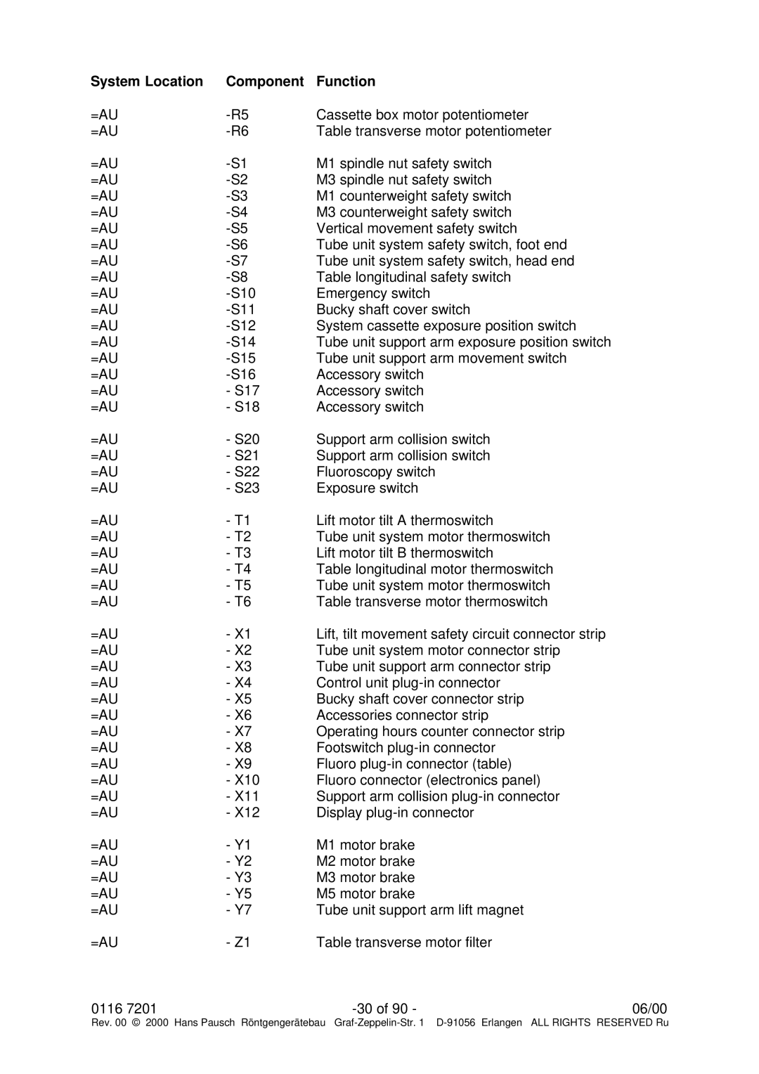
System Location | Component | Function |
=AU | Cassette box motor potentiometer | |
=AU | Table transverse motor potentiometer | |
=AU | M1 spindle nut safety switch | |
=AU | M3 spindle nut safety switch | |
=AU | M1 counterweight safety switch | |
=AU | M3 counterweight safety switch | |
=AU | Vertical movement safety switch | |
=AU | Tube unit system safety switch, foot end | |
=AU | Tube unit system safety switch, head end | |
=AU | Table longitudinal safety switch | |
=AU | Emergency switch | |
=AU | Bucky shaft cover switch | |
=AU | System cassette exposure position switch | |
=AU | Tube unit support arm exposure position switch | |
=AU | Tube unit support arm movement switch | |
=AU | Accessory switch | |
=AU | - S17 | Accessory switch |
=AU | - S18 | Accessory switch |
=AU | - S20 | Support arm collision switch |
=AU | - S21 | Support arm collision switch |
=AU | - S22 | Fluoroscopy switch |
=AU | - S23 | Exposure switch |
=AU | - T1 | Lift motor tilt A thermoswitch |
=AU | - T2 | Tube unit system motor thermoswitch |
=AU | - T3 | Lift motor tilt B thermoswitch |
=AU | - T4 | Table longitudinal motor thermoswitch |
=AU | - T5 | Tube unit system motor thermoswitch |
=AU | - T6 | Table transverse motor thermoswitch |
=AU | - X1 | Lift, tilt movement safety circuit connector strip |
=AU | - X2 | Tube unit system motor connector strip |
=AU | - X3 | Tube unit support arm connector strip |
=AU | - X4 | Control unit |
=AU | - X5 | Bucky shaft cover connector strip |
=AU | - X6 | Accessories connector strip |
=AU | - X7 | Operating hours counter connector strip |
=AU | - X8 | Footswitch |
=AU | - X9 | Fluoro |
=AU | - X10 | Fluoro connector (electronics panel) |
=AU | - X11 | Support arm collision |
=AU | - X12 | Display |
=AU | - Y1 | M1 motor brake |
=AU | - Y2 | M2 motor brake |
=AU | - Y3 | M3 motor brake |
=AU | - Y5 | M5 motor brake |
=AU | - Y7 | Tube unit support arm lift magnet |
=AU | - Z1 | Table transverse motor filter |
0116 7201 | 06/00 |
Rev. 00 © 2000 Hans Pausch Röntgengerätebau Graf