Place the assembled tube unit – collimator combination (Fig. 17/Pos. 1) on the tube unit support arm (Fig. 18/Pos. 2) using the support studs (Pos. 3), insert the shims (Fig. 16/ Pos. 5) and secure it in place using the 4 screws (Pos. 6).
2.10 Installing the Image Intensifier
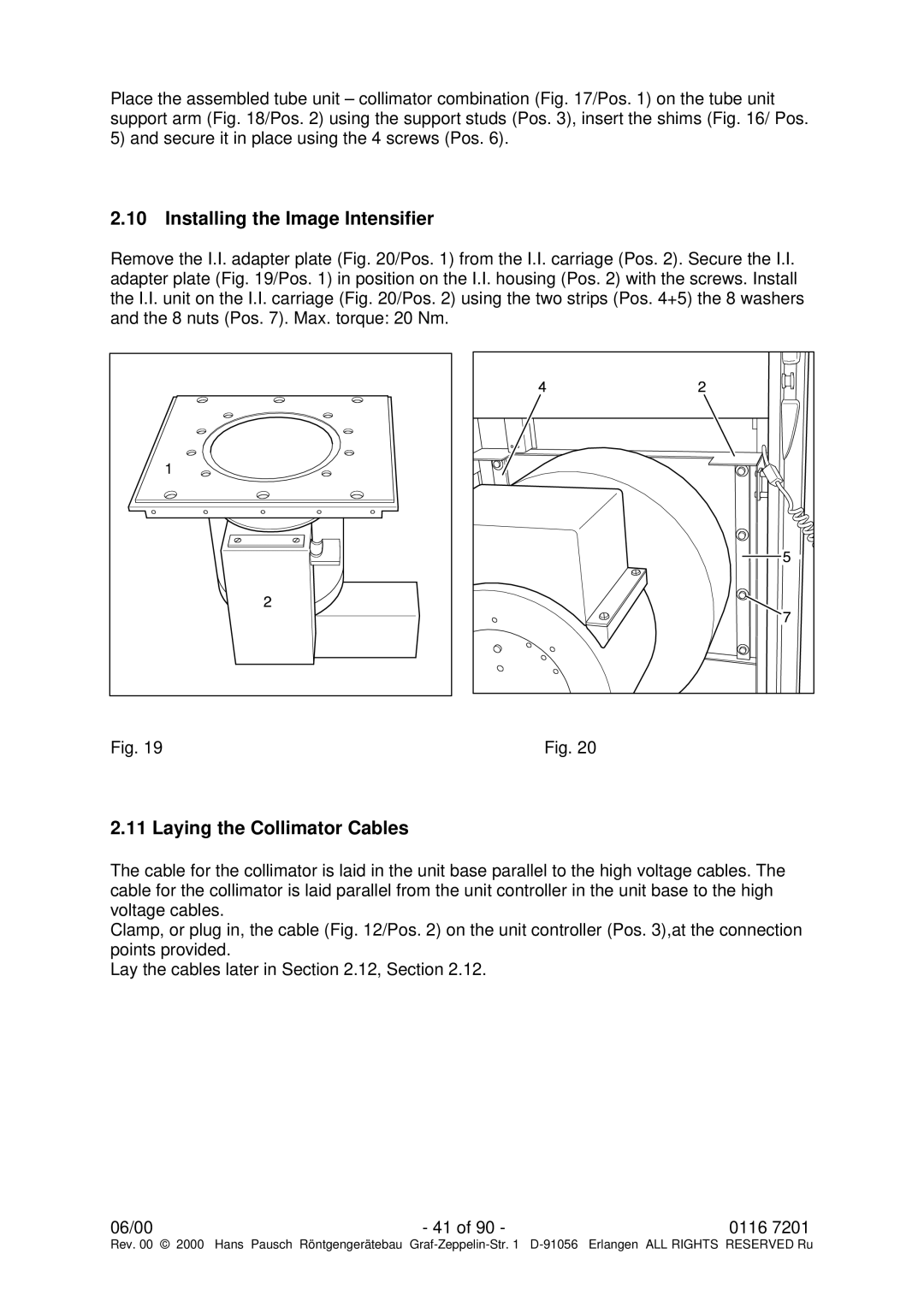
Remove the I.I. adapter plate (Fig. 20/Pos. 1) from the I.I. carriage (Pos. 2). Secure the I.I. adapter plate (Fig. 19/Pos. 1) in position on the I.I. housing (Pos. 2) with the screws. Install the I.I. unit on the I.I. carriage (Fig. 20/Pos. 2) using the two strips (Pos. 4+5) the 8 washers and the 8 nuts (Pos. 7). Max. torque: 20 Nm.
Fig. 19 | Fig. 20 |
2.11 Laying the Collimator Cables
The cable for the collimator is laid in the unit base parallel to the high voltage cables. The cable for the collimator is laid parallel from the unit controller in the unit base to the high voltage cables.
Clamp, or plug in, the cable (Fig. 12/Pos. 2) on the unit controller (Pos. 3),at the connection points provided.
Lay the cables later in Section 2.12, Section 2.12.
06/00 | - 41 of 90 - | 0116 7201 |
Rev. 00 © 2000 Hans Pausch Röntgengerätebau Graf