3.2Central Beam - Center of Bucky
Determine the deviation of the central beam.
Transverse to the tabletop, for this:
Caution:
Risk of an accident exists here because the tube unit must be loosened.
Remove the cover panel (Fig. 52/Pos. 6). Remove the mounting screws (Fig. 52/Pos. 1), remove the shims (Pos. 2) for the tube unit and insert them to compensate for any difference in the central beam. Reinstall the mounting screws (Pos. 1).
Lengthwise to the tabletop, for this:
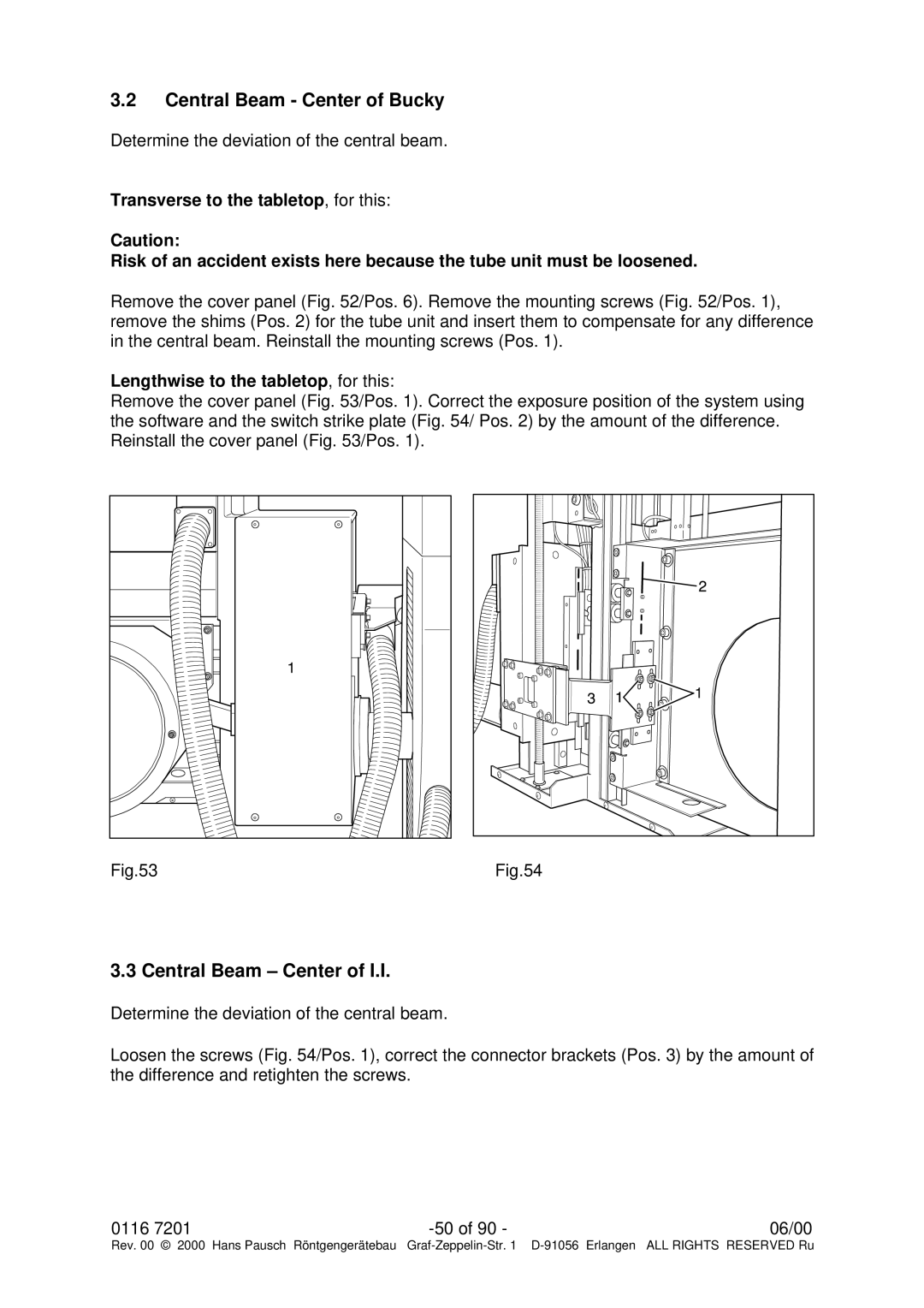
Remove the cover panel (Fig. 53/Pos. 1). Correct the exposure position of the system using the software and the switch strike plate (Fig. 54/ Pos. 2) by the amount of the difference. Reinstall the cover panel (Fig. 53/Pos. 1).
Fig.53 |
Fig.54 |
3.3 Central Beam – Center of I.I.
Determine the deviation of the central beam.
Loosen the screws (Fig. 54/Pos. 1), correct the connector brackets (Pos. 3) by the amount of the difference and retighten the screws.
0116 7201 | 06/00 |
Rev. 00 © 2000 Hans Pausch Röntgengerätebau Graf