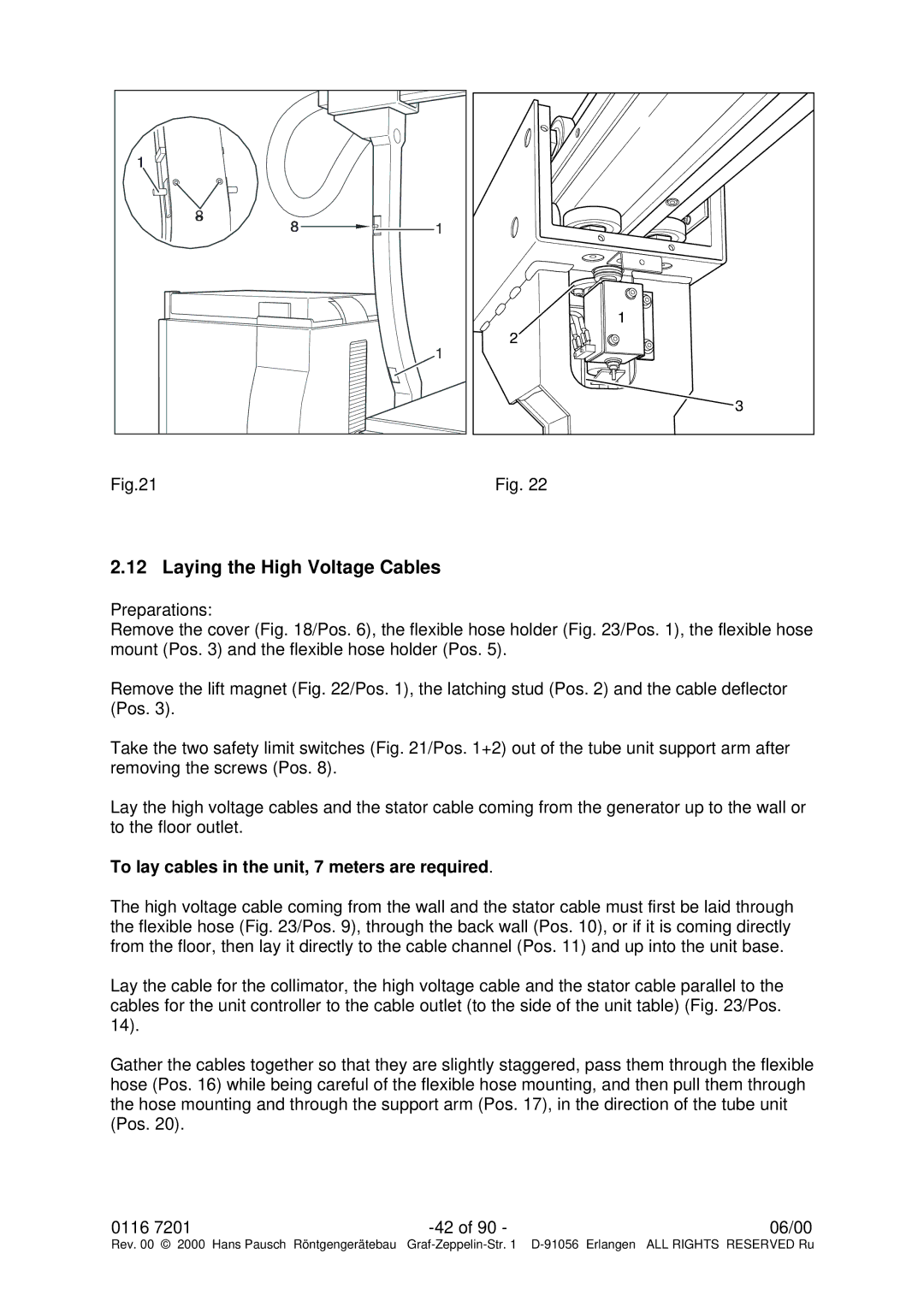
Fig.21 | Fig. 22 |
2.12 Laying the High Voltage Cables
Preparations:
Remove the cover (Fig. 18/Pos. 6), the flexible hose holder (Fig. 23/Pos. 1), the flexible hose mount (Pos. 3) and the flexible hose holder (Pos. 5).
Remove the lift magnet (Fig. 22/Pos. 1), the latching stud (Pos. 2) and the cable deflector (Pos. 3).
Take the two safety limit switches (Fig. 21/Pos. 1+2) out of the tube unit support arm after removing the screws (Pos. 8).
Lay the high voltage cables and the stator cable coming from the generator up to the wall or to the floor outlet.
To lay cables in the unit, 7 meters are required.
The high voltage cable coming from the wall and the stator cable must first be laid through the flexible hose (Fig. 23/Pos. 9), through the back wall (Pos. 10), or if it is coming directly from the floor, then lay it directly to the cable channel (Pos. 11) and up into the unit base.
Lay the cable for the collimator, the high voltage cable and the stator cable parallel to the cables for the unit controller to the cable outlet (to the side of the unit table) (Fig. 23/Pos. 14).
Gather the cables together so that they are slightly staggered, pass them through the flexible hose (Pos. 16) while being careful of the flexible hose mounting, and then pull them through the hose mounting and through the support arm (Pos. 17), in the direction of the tube unit (Pos. 20).
0116 7201 | 06/00 | |
Rev. 00 © 2000 Hans Pausch Röntgengerätebau | Graf |