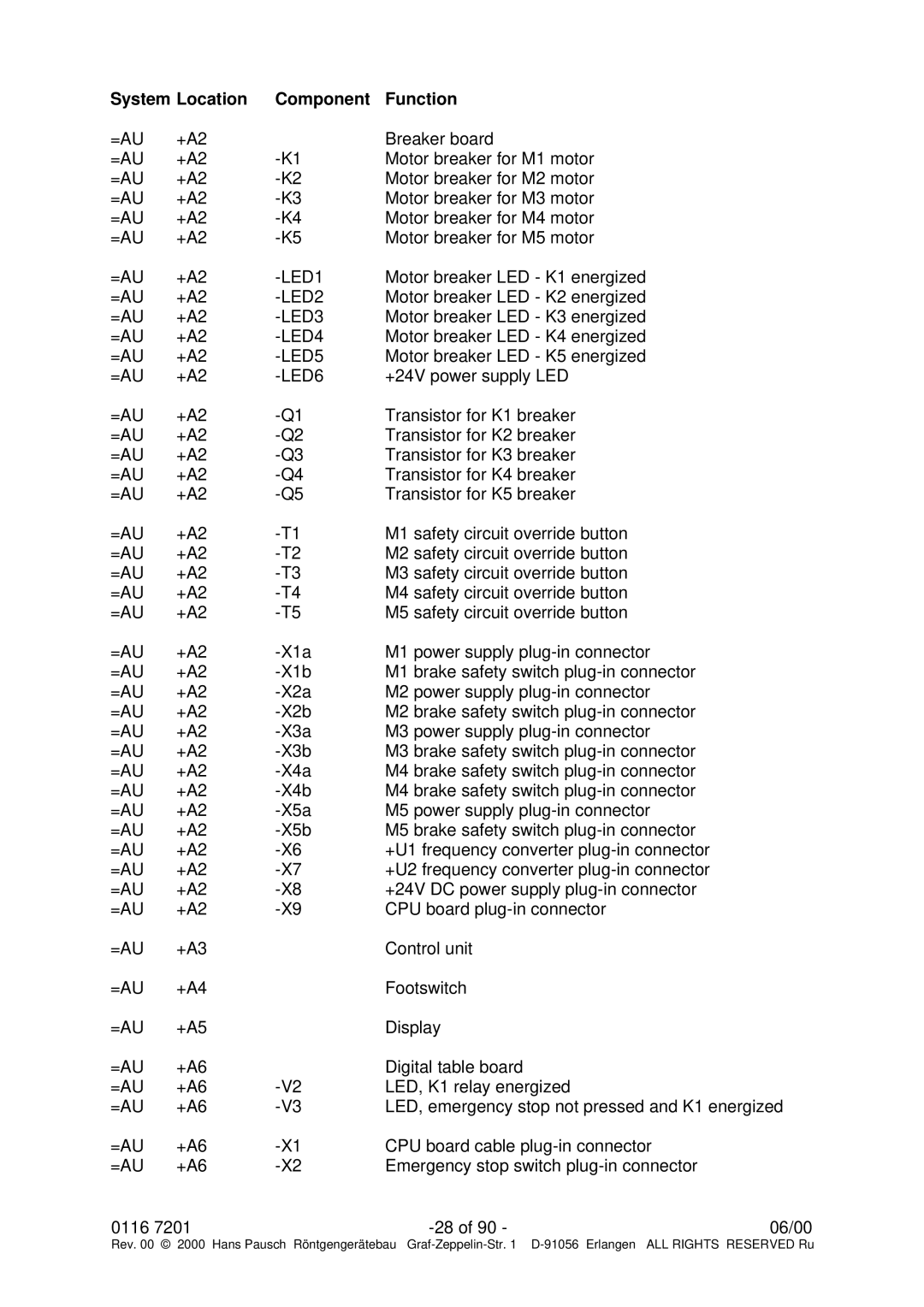
System Location | Component | Function |
| |
=AU | +A2 |
| Breaker board |
|
=AU | +A2 | Motor breaker for M1 motor |
| |
=AU | +A2 | Motor breaker for M2 motor |
| |
=AU | +A2 | Motor breaker for M3 motor |
| |
=AU | +A2 | Motor breaker for M4 motor |
| |
=AU | +A2 | Motor breaker for M5 motor |
| |
=AU | +A2 |
| Motor breaker LED - K1 energized |
|
=AU | +A2 | Motor breaker LED - K2 energized |
| |
=AU | +A2 | Motor breaker LED - K3 energized |
| |
=AU | +A2 | Motor breaker LED - K4 energized |
| |
=AU | +A2 | Motor breaker LED - K5 energized |
| |
=AU | +A2 | +24V power supply LED |
| |
=AU | +A2 | Transistor for K1 breaker |
| |
=AU | +A2 | Transistor for K2 breaker |
| |
=AU | +A2 | Transistor for K3 breaker |
| |
=AU | +A2 | Transistor for K4 breaker |
| |
=AU | +A2 | Transistor for K5 breaker |
| |
=AU | +A2 | M1 safety circuit override button |
| |
=AU | +A2 | M2 safety circuit override button |
| |
=AU | +A2 | M3 safety circuit override button |
| |
=AU | +A2 | M4 safety circuit override button |
| |
=AU | +A2 | M5 safety circuit override button |
| |
=AU | +A2 | M1 power supply |
| |
=AU | +A2 | M1 brake safety switch |
| |
=AU | +A2 | M2 power supply |
| |
=AU | +A2 | M2 brake safety switch |
| |
=AU | +A2 | M3 power supply |
| |
=AU | +A2 | M3 brake safety switch |
| |
=AU | +A2 | M4 brake safety switch |
| |
=AU | +A2 | M4 brake safety switch |
| |
=AU | +A2 | M5 power supply |
| |
=AU | +A2 | M5 brake safety switch |
| |
=AU | +A2 | +U1 frequency converter |
| |
=AU | +A2 | +U2 frequency converter |
| |
=AU | +A2 | +24V DC power supply |
| |
=AU | +A2 | CPU board |
| |
=AU | +A3 |
| Control unit |
|
=AU | +A4 |
| Footswitch |
|
=AU | +A5 |
| Display |
|
=AU | +A6 |
| Digital table board |
|
=AU | +A6 | LED, K1 relay energized |
| |
=AU | +A6 | LED, emergency stop not pressed and K1 energized | ||
=AU | +A6 | CPU board cable |
| |
=AU | +A6 | Emergency stop switch |
| |
0116 7201 |
| 06/00 | ||
Rev. 00 © 2000 Hans Pausch Röntgengerätebau Graf
