8.0 Input Channels
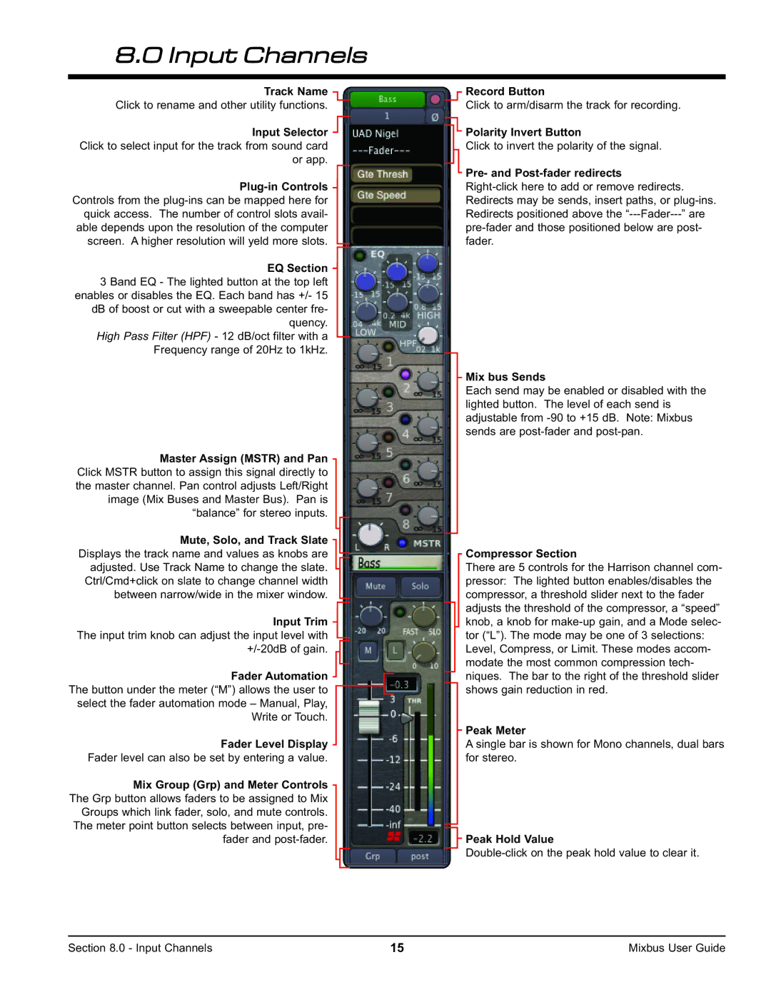
Track Name Click to rename and other utility functions.
Input Selector Click to select input for the track from sound card or app.
EQ Section 3 Band EQ - The lighted button at the top left enables or disables the EQ. Each band has +/- 15 dB of boost or cut with a sweepable center fre- quency.
High Pass Filter (HPF) - 12 dB/oct filter with a Frequency range of 20Hz to 1kHz.
Master Assign (MSTR) and Pan Click MSTR button to assign this signal directly to the master channel. Pan control adjusts Left/Right image (Mix Buses and Master Bus). Pan is “balance” for stereo inputs.
Mute, Solo, and Track Slate Displays the track name and values as knobs are adjusted. Use Track Name to change the slate. Ctrl/Cmd+click on slate to change channel width between narrow/wide in the mixer window.
Input Trim The input trim knob can adjust the input level with
Fader Automation The button under the meter (“M”) allows the user to select the fader automation mode – Manual, Play, Write or Touch.
Fader Level Display Fader level can also be set by entering a value.
Mix Group (Grp) and Meter Controls The Grp button allows faders to be assigned to Mix Groups which link fader, solo, and mute controls. The meter point button selects between input, pre- fader and
Record Button
Click to arm/disarm the track for recording.
Polarity Invert Button
Click to invert the polarity of the signal.
Pre- and Post-fader redirects
Mix bus Sends
Each send may be enabled or disabled with the lighted button. The level of each send is adjustable from
Compressor Section
There are 5 controls for the Harrison channel com- pressor: The lighted button enables/disables the compressor, a threshold slider next to the fader adjusts the threshold of the compressor, a “speed” knob, a knob for
Peak Meter
A single bar is shown for Mono channels, dual bars for stereo.
Peak Hold Value
Section 8.0 - Input Channels | 15 | Mixbus User Guide |
