Mounting and Wiring the Control
Installing the RF Receiver
You can any ADEMCO 5800 Series Wireless Receivers, including:
RF Receiver | No. of Zones |
5881L/5882L | up to 8 |
5881M/5882M | up to 16 (transmitter zone numbers = |
5883, 6150RF | up to 16 (transmitter zone numbers = |
|
|
1.Set Device Address to “00” as described in its instructions (set all switches to the right, “off” position).
2.Mount the receiver, noting that the RF receiver can detect signals from transmitters within a nominal range of 200 feet.
3.Connect the receiver's wire harness to the control's keypad terminals. Plug the connector at the other end of the harness into the receiver. Refer to the installation instructions provided with the receiver for further installation procedures regarding antenna mounting, etc.
NOTES
•The receiver is supervised and a trouble report is sent (“CHECK 100” displayed) if communication between the panel and receiver is interrupted, or if no valid RF signals from at least one supervised
transmitter are received within 12 hours. If the receiver is mounted remotely:
•Place the RF receiver in a high, centrally located area for best reception.
•Do not locate the receiver or transmitters on or near metal objects. This will decrease range and/or block transmissions.
•Do not locate the RF receiver in an area of high RF interference (indicated by frequent or prolonged lighting of the LED in the receiver; random flicker is OK).
•Do not locate RF receiver closer than 10 feet from any keypads to avoid interference from the microprocessors in those units.
NOTE
CIRCUIT BOARD IS MOUNTED IN CONTROL'S CABINET. GROUNDING LUGS (2) PROVIDED MUST BE INSERTED IN
MOUNTING
HOLES
ANTENNAS
(INSERT IN
TERMINALS)
INSERT IN
RIGHT- HAND
TERMINALS
![]() MODEL NO. IS INDICATED ON CIRCUIT BOARD
MODEL NO. IS INDICATED ON CIRCUIT BOARD ![]()
5882 | DIP |
LOCATION | SWITCH |
INTERFERENCE
INDICATOR
LED
CIRCUIT BOARD
YELLOW |
|
|
| TO CONTROL'S |
RED |
|
|
| |
|
|
| REMOTE KEYPAD | |
BLACK |
|
|
| |
|
|
| CONNECTION | |
GREEN |
|
|
| |
|
|
| POINTS. | |
|
|
|
|
![]() WIRING OPENING
WIRING OPENING
KNOCKOUT AREA
FOR SURFACE WIRING
SOCKET | PLUG |
TO RELEASE CIRCUIT BOARD, |
|
REMOVE SCREWS AND |
|
BEND BACK TABS |
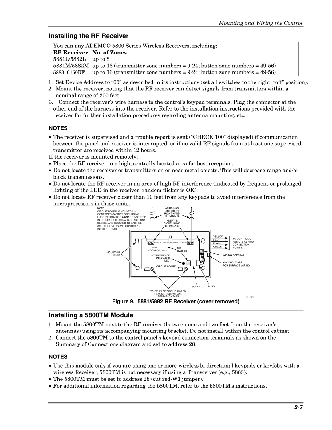
Figure 9. 5881/5882 RF Receiver (cover removed)
Installing a 5800TM Module
1.Mount the 5800TM next to the RF receiver (between one and two feet from the receiver’s antennas) using its accompanying mounting bracket. Do not install within the control cabinet.
2.Connect the 5800TM to the control panel’s keypad connection terminals as shown on the Summary of Connections diagram and set to address 28.
NOTES
•Use this module only if you are using one or more wireless
•The 5800TM must be set to address 28 (cut
•For additional information regarding the 5800TM, refer to the 5800TM’s instructions.