Installation Instructions
Panic Keys
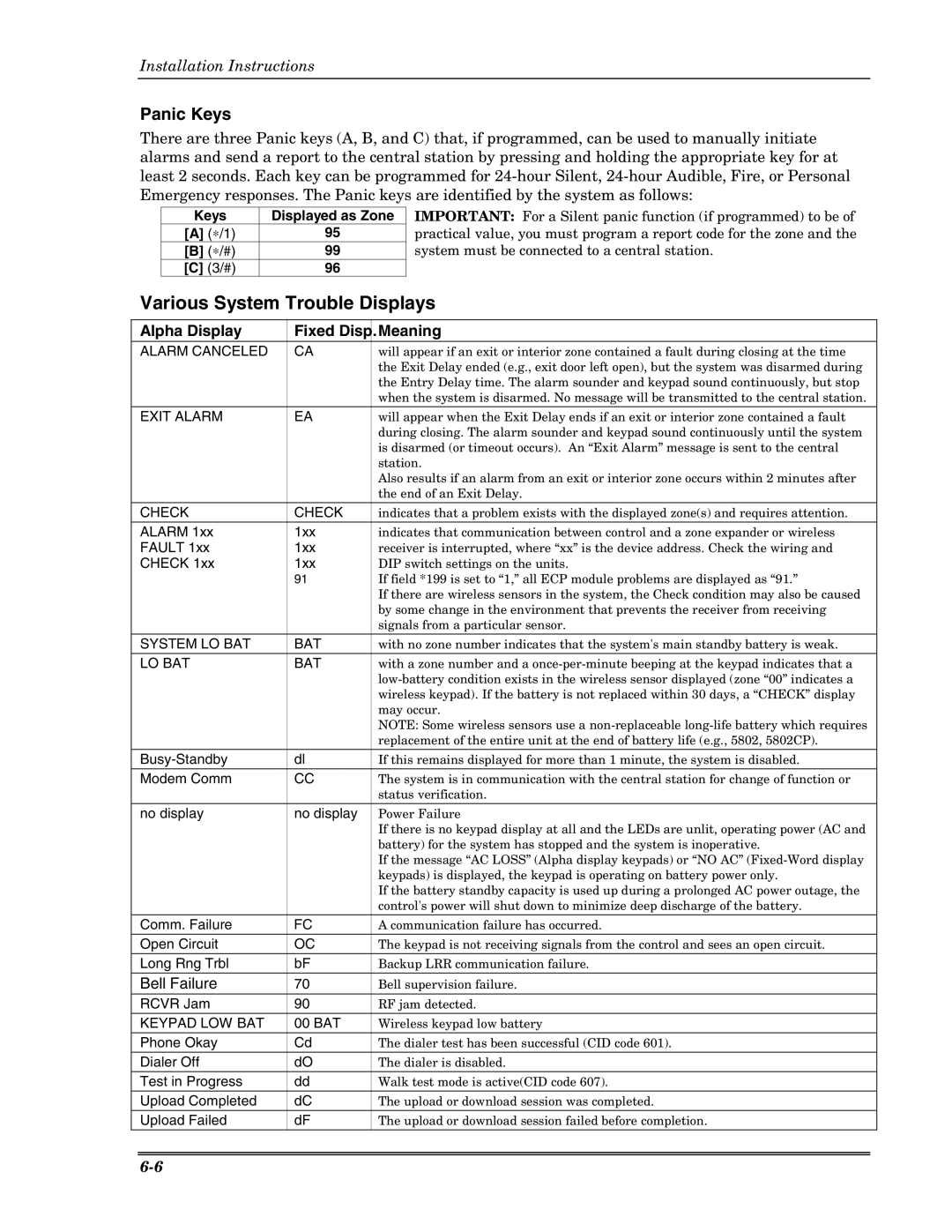
There are three Panic keys (A, B, and C) that, if programmed, can be used to manually initiate alarms and send a report to the central station by pressing and holding the appropriate key for at least 2 seconds. Each key can be programmed for
Keys | Displayed as Zone |
[A] (∗/1) | 95 |
[B] (∗/#) | 99 |
[C] (3/#) | 96 |
IMPORTANT: For a Silent panic function (if programmed) to be of practical value, you must program a report code for the zone and the system must be connected to a central station.
Various System Trouble Displays
Alpha Display | Fixed Disp. | Meaning |
ALARM CANCELED | CA | will appear if an exit or interior zone contained a fault during closing at the time |
|
| the Exit Delay ended (e.g., exit door left open), but the system was disarmed during |
|
| the Entry Delay time. The alarm sounder and keypad sound continuously, but stop |
|
| when the system is disarmed. No message will be transmitted to the central station. |
EXIT ALARM | EA | will appear when the Exit Delay ends if an exit or interior zone contained a fault |
|
| during closing. The alarm sounder and keypad sound continuously until the system |
|
| is disarmed (or timeout occurs). An “Exit Alarm” message is sent to the central |
|
| station. |
|
| Also results if an alarm from an exit or interior zone occurs within 2 minutes after |
|
| the end of an Exit Delay. |
CHECK | CHECK | indicates that a problem exists with the displayed zone(s) and requires attention. |
ALARM 1xx | 1xx | indicates that communication between control and a zone expander or wireless |
FAULT 1xx | 1xx | receiver is interrupted, where “xx” is the device address. Check the wiring and |
CHECK 1xx | 1xx | DIP switch settings on the units. |
| 91 | If field *199 is set to “1,” all ECP module problems are displayed as “91.” |
|
| If there are wireless sensors in the system, the Check condition may also be caused |
|
| by some change in the environment that prevents the receiver from receiving |
|
| signals from a particular sensor. |
SYSTEM LO BAT | BAT | with no zone number indicates that the system's main standby battery is weak. |
LO BAT | BAT | with a zone number and a |
|
| |
|
| wireless keypad). If the battery is not replaced within 30 days, a “CHECK” display |
|
| may occur. |
|
| NOTE: Some wireless sensors use a |
|
| replacement of the entire unit at the end of battery life (e.g., 5802, 5802CP). |
dl | If this remains displayed for more than 1 minute, the system is disabled. | |
Modem Comm | CC | The system is in communication with the central station for change of function or |
|
| status verification. |
no display | no display | Power Failure |
|
| If there is no keypad display at all and the LEDs are unlit, operating power (AC and |
|
| battery) for the system has stopped and the system is inoperative. |
|
| If the message “AC LOSS” (Alpha display keypads) or “NO AC” |
|
| keypads) is displayed, the keypad is operating on battery power only. |
|
| If the battery standby capacity is used up during a prolonged AC power outage, the |
|
| control's power will shut down to minimize deep discharge of the battery. |
Comm. Failure | FC | A communication failure has occurred. |
Open Circuit | OC | The keypad is not receiving signals from the control and sees an open circuit. |
Long Rng Trbl | bF | Backup LRR communication failure. |
Bell Failure | 70 | Bell supervision failure. |
RCVR Jam | 90 | RF jam detected. |
KEYPAD LOW BAT | 00 BAT | Wireless keypad low battery |
Phone Okay | Cd | The dialer test has been successful (CID code 601). |
Dialer Off | dO | The dialer is disabled. |
Test in Progress | dd | Walk test mode is active(CID code 607). |
Upload Completed | dC | The upload or download session was completed. |
Upload Failed | dF | The upload or download session failed before completion. |
