Installation Instructions
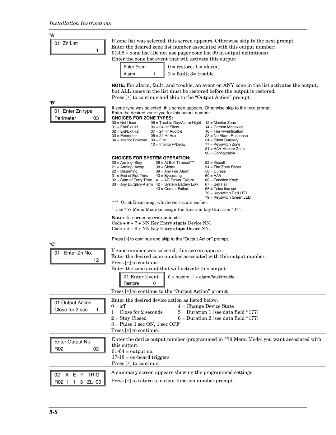
“A”
01 Zn List
1
If zone list was selected, this screen appears. Otherwise skip to the next prompt. Enter the desired zone list number associated with this output number:
Enter Event |
| 0 | = restore; 1 = alarm; |
Alarm | 1 | 2 | = fault; 3= trouble |
“B”
01Enter Zn type
Perimeter 03
NOTE: For alarm, fault, and trouble, an event on ANY zone in the list activates the output, but ALL zones in the list must be restored before the output is restored.
Press [∗] to continue and skip to the “Output Action” prompt.
If zone type was selected, this screen appears. Otherwise skip to the next prompt. Enter the desired zone type for this output number.
CHOICES FOR ZONE TYPES:
00 | = Not Used | 05 | = Trouble Day/Alarm Night | 12 | = Monitor Zone | |
01 | = Ent/Exit #1 | 06 | = 24 | Hr Silent | 14 | = Carbon Monoxide |
02 | = Ent/Exit #2 | 07 | = 24 | Hr Audible | 16 | = Fire w/verification |
03 | = Perimeter | 08 | = 24 | Hr Aux | 23 | = No Alarm Response |
04 | = Interior Follower | 09 | = Fire | 24 | = Silent Burglary | |
|
| 10 | = Interior w/Delay | 77 | = Keyswitch Zone | |
|
|
|
|
| 81 | = AAV Monitor Zone |
|
|
|
|
| 90 | = Configurable |
CHOICES FOR SYSTEM OPERATION:
“C”
01 Enter Zn No.
12
20 | = | 36 | = At Bell Timeout*** | 52 | = Kissoff |
21 | = | 38 | = Chime | 54 | = Fire Zone Reset |
22 | = Disarming | 39 | = Any Fire Alarm | 58 | = Duress |
31 | = End of Exit Time | 40 | = Bypassing | 60 | = AAV |
32 | = Start of Entry Time | 41 | = AC Power Failure | 66 | = Function Key† |
33 | = Any Burglary Alarm | 42 | = System Battery Low | 67 | = Bell Fail |
|
| 43 | = Comm. Failure | 68 | = Telco line cut |
|
|
|
| 78 | = Keyswitch Red LED |
|
|
|
| 79 | = Keyswitch Green LED |
*** Or at Disarming, whichever occurs earlier.
† Use *57 Menu Mode to assign the function key (function “07”).
Note: In normal operation mode:
Code + # + 7 + NN Key Entry starts Device NN.
Code + # + 8 + NN Key Entry stops Device NN.
Press [∗] to continue and skip to the “Output Action” prompt.
If zone number was selected, this screen appears.
Enter the desired zone number associated with this output number. Press [∗] to continue.
Enter the zone event that will activate this output.
01 Enter Event
Restore 0
0 = restore; 1 = alarm/fault/trouble
Press [∗] to continue to the “Output Action” prompt
01 Output Action |
|
Close for 2 sec | 1 |
Enter the desired device action as listed below.
0 | = off | 4 | = Change Device State | |
1 | = Close for 2 seconds | 5 | = Duration 1 | (see data field *177) |
2 | = Stay Closed | 6 = Duration 2 | (see data field *177) | |
3 | = Pulse 1 sec ON, 1 sec OFF |
|
| |
Press [∗] to continue.
Enter Output No.
R0202
Enter the device output number (programmed in *79 Menu Mode) you want associated with this output.
02A E P TRIG
R02 1 1 3 ZL=00
A summary screen appears showing the programmed settings. Press [∗] to return to output function number prompt.