Mounting and Wiring the Control
Wiring to Keypads
1.Connect keypads to the keypad terminals as shown on the Summary of Connections diagram. Determine wire size using the Wire Run Chart below.
2.Set keypad addresses. Refer to the address setting instructions included with the keypads and set each keypad device address according to the chart at right.
3.Program the keypad addresses and sound options in data fields
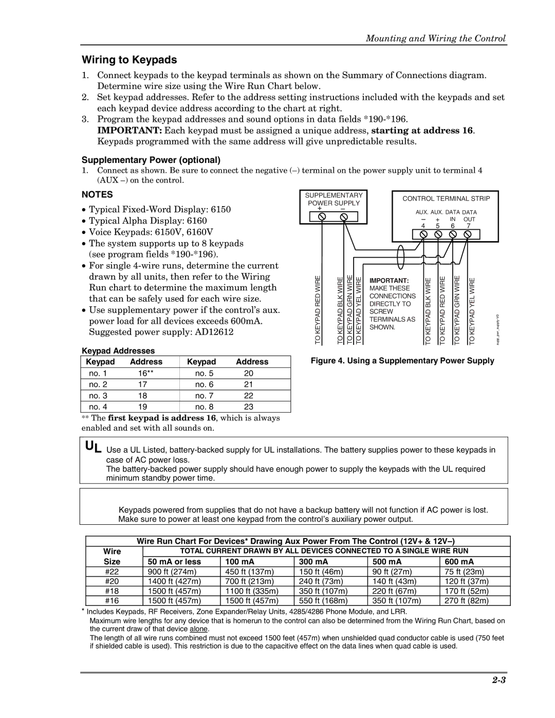
Supplementary Power (optional)
1.Connect as shown. Be sure to connect the negative
NOTES
• Typical |
• Typical Alpha Display: 6160 |
• Voice Keypads: 6150V, 6160V |
• The system supports up to 8 keypads |
(see program fields |
• For single |
SUPPLEMENTARY |
| CONTROL TERMINAL STRIP | |||||||
POWER SUPPLY |
| ||||||||
|
|
|
|
|
|
|
| ||
+ | – |
| AUX. AUX. DATA DATA | ||||||
|
|
| |||||||
|
|
|
| – | + |
| IN | OUT | |
|
|
| 4 | 5 | 6 | 7 | |||
|
|
|
|
|
|
|
|
|
|
|
|
|
|
|
|
|
|
|
|
|
|
|
|
|
|
|
|
|
|
|
|
|
|
|
|
|
|
|
|
|
|
|
|
|
|
|
|
|
|
|
|
|
|
|
|
|
|
|
|
|
|
|
|
|
|
|
|
|
|
drawn by all units, then refer to the Wiring |
Run chart to determine the maximum length |
that can be safely used for each wire size. |
• Use supplementary power if the control’s aux. |
power load for all devices exceeds 600mA. |
Suggested power supply: AD12612 |
RED WIRE | BLK WIRE | GRN WIRE | YEL WIRE |
TO KEYPAD | TO KEYPAD | TO KEYPAD | TO KEYPAD |
IMPORTANT:
MAKE THESE CONNECTIONS DIRECTLY TO SCREW TERMINALS AS SHOWN.
TO KEYPAD BLK WIRE
TO KEYPAD RED WIRE
GRN WIRE | YEL WIRE |
TO KEYPAD | TO KEYPAD |
Keypad Addresses |
|
|
| |
Keypad | Address | Keypad | Address | Figure 4. Using a Supplementary Power Supply |
no. 1 | 16** | no. 5 | 20 |
|
no. 2 | 17 | no. 6 | 21 |
|
no. 3 | 18 | no. 7 | 22 |
|
no. 4 | 19 | no. 8 | 23 |
|
**The first keypad is address 16, which is always enabled and set with all sounds on.
UL Use a UL Listed,
The
Keypads powered from supplies that do not have a backup battery will not function if AC power is lost. Make sure to power at least one keypad from the control’s auxiliary power output.
Wire Run Chart For Devices* Drawing Aux Power From The Control (12V+ &
Wire | TOTAL CURRENT DRAWN BY ALL DEVICES CONNECTED TO A SINGLE WIRE RUN | ||||
Size | 50 mA or less | 100 mA | 300 mA | 500 mA | 600 mA |
#22 | 900 ft (274m) | 450 ft (137m) | 150 ft (46m) | 90 ft (27m) | 75 ft (23m) |
#20 | 1400 ft (427m) | 700 ft (213m) | 240 ft (73m) | 140 ft (43m) | 120 ft (37m) |
#18 | 1500 ft (457m) | 1100 ft (335m) | 350 ft (107m) | 220 ft (67m) | 170 ft (52m) |
#16 | 1500 ft (457m) | 1500 ft (457m) | 550 ft (168m) | 350 ft (107m) | 270 ft (82m) |
*Includes Keypads, RF Receivers, Zone Expander/Relay Units, 4285/4286 Phone Module, and LRR.
Maximum wire lengths for any device that is homerun to the control can also be determined from the Wiring Run Chart, based on the current draw of that device alone.
The length of all wire runs combined must not exceed 1500 feet (457m) when unshielded quad conductor cable is used (750 feet if shielded cable is used). This restriction is due to the capacitive effect on the data lines when quad cable is used.