Ademco VISTA-10P Ademco VISTA-10PSIA
Recommendations for Proper Protection
Table Of Contents
Menu Mode Programming
Testing the System
System Communication and Operation
Compatible Devices
Features and Installation Highlights
Capabilities
Functions
Important Installation Highlights Installer Please Read
Mounting and Wiring the Control
Cabinet and Lock
Mounting the PC Board Alone no RF Receiver
Mounting the PC Board and RF Receiver
Mounting Board with RF Receiver
Size MA or less 100 mA 300 mA 500 mA 600 mA
Wiring to Keypads
Supplementary Power optional
Keypad Addresses
Distance from control Wire Size
Wiring the AC Transformer
Backup Battery
Wire Run Chart
AC Power Outlet Ground
Earth Ground
Metal Cold Water Pipe
Normally Open Zones/ Normally Open Eolr Zones
Hardwire Zones
Wire Smoke Detectors
Smoke Detectors
Installing the RF Receiver
Installing a 5800TM Module
RF Receiver No. of Zones
Installing the Transmitters
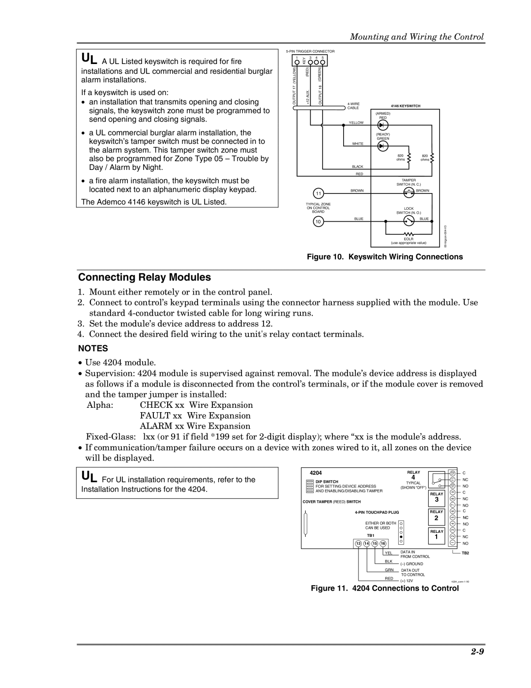
Installing a Keyswitch
Transmitter Battery Life
Keyswitch Wiring Connections
Connecting Relay Modules
On-Board Trigger Connector with 4-Wire Cable
On-Board Triggers
Phone Line/Phone Module Connections
Long Range Radio Connections
Phone Module Problems
RJ31X
Audio Alarm Verification Connections AAV, listen-In
Keypads
To enable keypads
Programming Overview
About Programming
Output Devices
Wireless Receiver, Transmitters, and Wireless Keys keyfobs
Pager Programming
Function Keys
Zone Type Definitions
Monitor Zone
No Alarm Response
Keyswitch
Configurable
Task Procedure
Menu Mode Programming ∗56, *57, ∗58, ∗79, ∗80, ∗81, ∗82
Loading Factory Defaults/Initializing for Download
Exiting the Programming Mode
Table of Device Addresses
Reports as†† Enabled By…
Programming Data Fields
System Setup Fields
Data Field Programming
About Data Field Programming
Zone Sounds & Timing
Dialer Programming
System Status Report Codes
Bypass Restore Report Code
Cancel Report Code
Alarm Restore Report Code
Trouble Restore Report Code
Miscellaneous System Fields
No. of Reports In Armed Period per Zone Swinger Suppression
Event Log Enables
Event Log Full Report Code
Option Selection
Pager Programming Fields
Zone Type 90 Report Codes
Configurable Zone Type Programming Fields
Configurable Zone Type
Configurable Zone Type Options
Zone Conditions Represented Entries
Configurable Zone Type Charts
Keypad Programming Fields
Installation Instructions
SET to CONFIRM? 0 = no 1 = YES
Menu Mode Programming
Zone Programming Procedure
Zone Programming Overview ∗56 and ∗58 Menu Modes
Xmit to Confirm
Input Type RF Trans
Input S/N L
Input S/N
∗58 Expert Programming Mode Procedures
Completing Zone Programming
Program ALPHA? 0 = no 1 = YES
Wireless Key Programming Templates
RC in L
Template ?
Xmit to Confirm Press to Skip
Wireless Key Predefined Default Templates
Wireless Key Transmitter
Input S/N AXXX-XXXX
Output Device programming involves
Output Device Programming Overview *79/*80 Menu Mode
Menu Mode Output Device Mapping
∗79 Menu Mode
Prompt Entry
Menu Mode Defining Output Functions
∗80 Menu Mode
Output Definition Components
E P Trig
List No Used for…
Zone List Overview ∗81 Menu Mode
Menu Mode
Zone List Programming
Is no longer available to be used as an end
Function Key Programming Overview ∗57 Menu Mode
Programming Function Keys
Press the desired function key, A-D
About Descriptor Programming Overview ∗82 Menu Mode
Programming Zone Descriptors Menu mode ∗82
When defining descriptors
Custom?
ZN 01 Back D OOR
ZN 01 Back Door
ZN 01 Back Door
For Entering Zone Descriptors
Character Ascii Chart For Adding Custom Words
System Operation section
Programming Installer and User Schedules
= group number
Installation Instructions
System Communication and Operation
System Communication Overview
Report Code Formats
Code for Type +1/4+1 Report Standard Expanded
Where
Ademco Contact ID
Code Definition
Maximum
Setting the Real-Time Clock
User Security Codes
Level User No Functions
Function Description
Keypad Commands
Keypad Functions
Voice Keypads
Keys Displayed as Zone
Various System Trouble Displays
Alpha Display
Meaning
System Test
Testing the System
About Test Procedures
Checking Transmitter Enrollment Sniffer Mode
Automatic Periodic Test Report
Go/No Go Test Mode
Automatic Standby Battery Tests
Dialer Communication Test and Periodic Test Reports
Long Range Radio
Specifications & Accessories
Relay Module
Phone Modules
Series Transmitter Input Loop Identification
Compatible 5800 Series Transmitters Table
Model Product Input Type Description
Can be used to turn the burglary protection on and off
5827 Wireless Keypad
Installation Instructions
FCC Part
Industrie Canada
Federal Communications Commission FCC Part
Industry Canada
SIA Quick Reference Guide
UL Notices
Limitations of this Alarm System
Limitations and Warranty
10-2
Index
10-4
Summary of Connections
K0735V3 10/04 Rev. B
Limited Warranty