S E C T I O N 4
Data Field Programming
• • • • • • • • • • • • • • • • • • • • • • • • • • • • • • • • • • • •
About Data Field Programming
The following pages provide explanations of this control’s data fields and is intended to be used in conjunction with the Programming Guide. Refer to the Programming Guide for the specific option choices for each data field.
Use the blank programming form to record the data for this installation.
Programming Data Fields
Data field programming involves making the appropriate entries for each of the data fields. Start Data Field programming by entering the installer code + 8 + 0 + 0.
SIA Guidelines: Notes in certain data fields give instructions for programming the
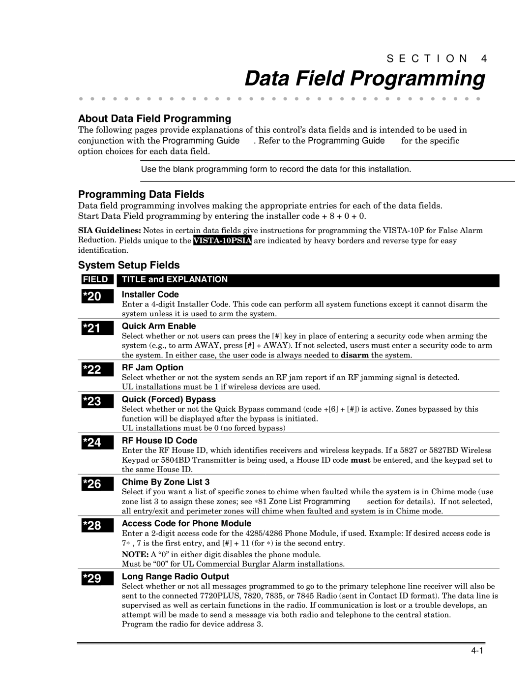
System Setup Fields
FIELD
*20
TITLE and EXPLANATION
Installer Code
Enter a
| *21 | Quick Arm Enable |
|
| Select whether or not users can press the [#] key in place of entering a security code when arming the |
|
| |
|
| system (e.g., to arm AWAY, press [#] + AWAY). If not selected, users must enter a security code to arm |
|
| the system. In either case, the user code is always needed to disarm the system. |
| *22 | RF Jam Option |
|
| Select whether or not the system sends an RF jam report if an RF jamming signal is detected. |
|
| |
|
| UL installations must be 1 if wireless devices are used. |
|
| Quick (Forced) Bypass |
| *23 | |
|
| Select whether or not the Quick Bypass command (code +[6] + [#]) is active. Zones bypassed by this |
|
| function will be displayed after the bypass is initiated. |
|
| UL installations must be 0 (no forced bypass) |
|
| RF House ID Code |
| *24 | |
|
| Enter the RF House ID, which identifies receivers and wireless keypads. If a 5827 or 5827BD Wireless |
|
| Keypad or 5804BD Transmitter is being used, a House ID code must be entered, and the keypad set to |
|
| the same House ID. |
|
| Chime By Zone List 3 |
| *26 | |
|
| Select if you want a list of specific zones to chime when faulted while the system is in Chime mode (use |
|
| zone list 3 to assign these zones; see ∗81 Zone List Programming section for details). If not selected, |
|
| all entry/exit and perimeter zones will chime when faulted and system is in Chime mode. |
|
| Access Code for Phone Module |
| *28 | |
|
| Enter a |
|
| 7∗ , 7 is the first entry, and [#] + 11 (for ∗) is the second entry. |
|
| NOTE: A “0” in either digit disables the phone module. |
|
| Must be “00” for UL Commercial Burglar Alarm installations. |
| *29 | Long Range Radio Output |
Select whether or not all messages programmed to go to the primary telephone line receiver will also be sent to the connected 7720PLUS, 7820, 7835, or 7845 Radio (sent in Contact ID format). The data line is supervised as well as certain functions in the radio. If communication is lost or a trouble develops, an attempt will be made to send a message via both radio and telephone to the central station.
Program the radio for device address 3.