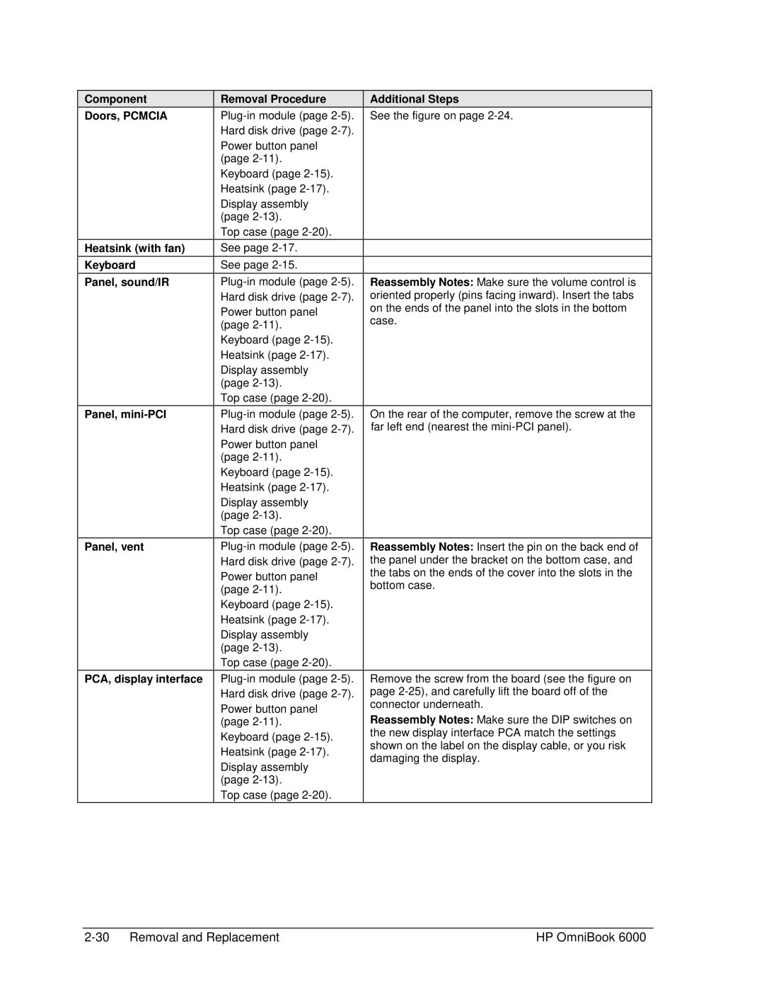
Component
Doors, PCMCIA
Heatsink (with fan)
Keyboard
Panel, sound/IR
Panel,
Panel, vent
PCA, display interface
Removal Procedure
Power button panel (page
Keyboard (page
Display assembly (page
Top case (page
See page
See page
Power button panel (page
Keyboard (page
Display assembly (page
Top case (page
Power button panel (page
Keyboard (page
Display assembly (page
Top case (page
Power button panel (page
Keyboard (page
Display assembly (page
Top case (page
Power button panel (page
Keyboard (page
Display assembly (page
Top case (page
Additional Steps
See the figure on page
Reassembly Notes: Make sure the volume control is oriented properly (pins facing inward). Insert the tabs on the ends of the panel into the slots in the bottom case.
On the rear of the computer, remove the screw at the far left end (nearest the
Reassembly Notes: Insert the pin on the back end of the panel under the bracket on the bottom case, and the tabs on the ends of the cover into the slots in the bottom case.
Remove the screw from the board (see the figure on page
Reassembly Notes: Make sure the DIP switches on the new display interface PCA match the settings shown on the label on the display cable, or you risk damaging the display.
| HP OmniBook 6000 |