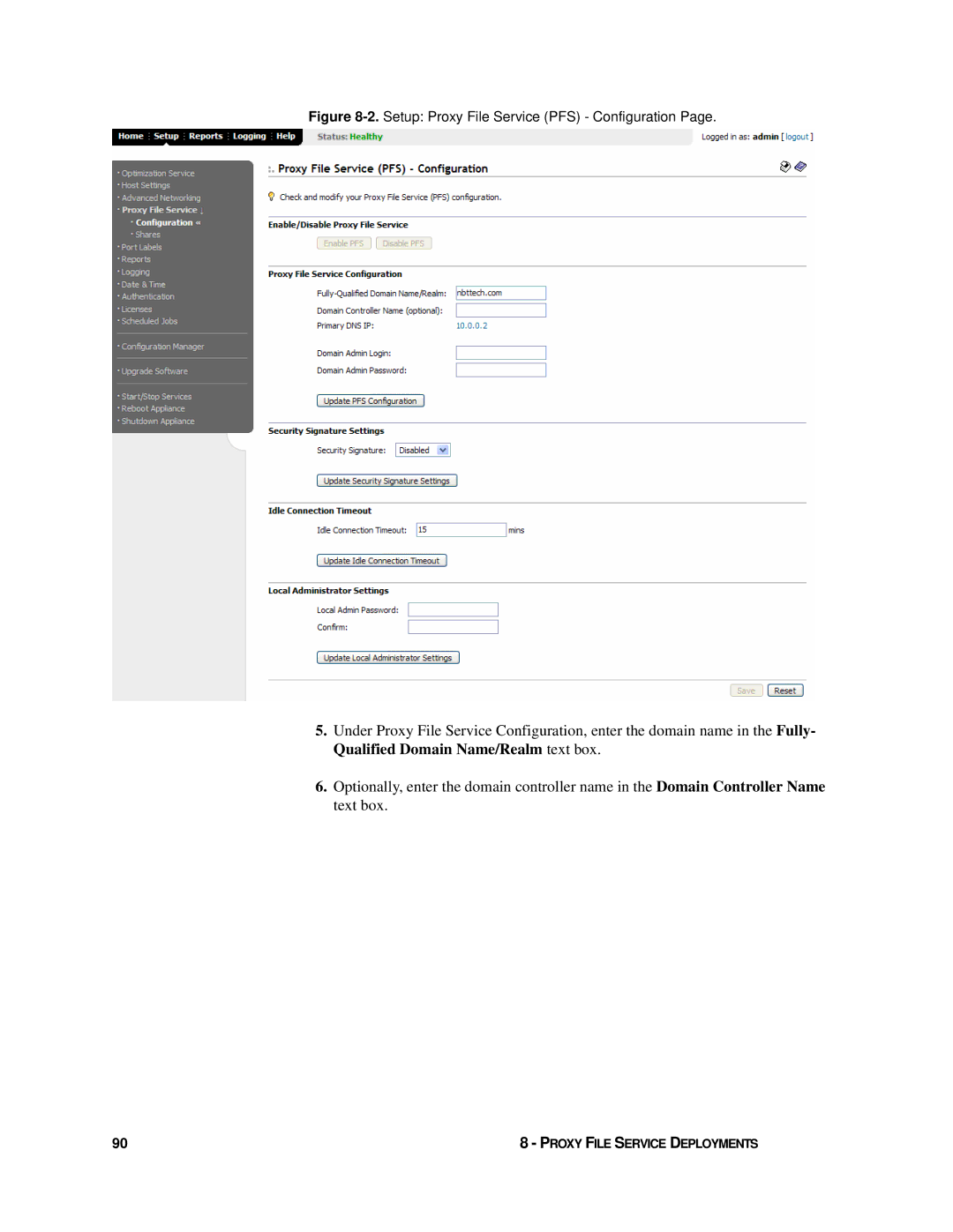
HP StorageWorks Enterprise File Services WAN Accelerator
407118-001
deployment guide
407118-002 Part number Second edition June
Enterprise File Services WAN Accelerator 2.1.5 deployment guide
Legal and notice information
Contents
Chapter 1 Designing an HP EFS WAN Accelerator Deployment
Chapter 2 In-Path Deployments
Chapter
Configuring Connection Forwarding
Chapter
Chapter
Chapter 6 Policy-Based Routing Deployments
Chapter 7 WCCP Deployments
Chapter 8 Proxy File Service Deployments
Chapter 9 RADIUS and TACACS+ Authentication
Chapter 10 Serial Cluster and Cascade Deployments
Glossary
Introduction
About This Guide
In This Introduction
“About This Guide,” next
Organization of This Guide
INTRODUCTION
Document Conventions
Courier
ntp peer addr version number
delete filename upload filename
Hardware and Software Dependencies
Ethernet Network Compatibility
Antivirus Compatibility
Additional Resources
“Related HP Documentation” on page “Online Documentation” on page
“Related Reading” on page
Related Reading
Related HP Documentation Online Documentation
Contacting HP
HP Storage Web Site
Technical Support
INTRODUCTION
CHAPTER 1 Designing an HP EFS WAN Accelerator Deployment
Introduction to the HP EFS WAN Accelerator
In This Chapter
“Introduction to the HP EFS WAN Accelerator” next
Transaction Acceleration
Scalable Data Referencing
Virtual Window Expansion
How Does SDR Work?
Design and Deployment Overview
Transaction Prediction
4. Choose a network template
Bypass Mode
Definition of Terms
Failover Mode
optimization is lost on the current connections on the master HP EFS WAN Accelerator
1 - DESIGNING AN HP EFS WAN ACCELERATOR DEPLOYMENT
Configuration Guide
CHAPTER 2 In-Path Deployments
“Introduction to Physical In-Path Deployments,” next
“In-Path, Failover Support Deployment” on page
Introduction to Physical In-Path Deployments
In-Path, Failover Support Deployment
Basic Steps Client-Side
4. Enable failover support. For example
In-Path, Two Routing Points Deployment
Basic Steps Server-Side
In-Path, Server-Side Deployment
Basic Steps Client-Side Basic Steps Server-Side
In-Path, Server-Side, One to One Deployment
Basic Steps Client-Side Basic Steps Server-Side
Figure 2-5. In-Path, Server-Side Deployment
Basic Steps Client-Side Basic Steps Server-Side
Figure 2-6. In-Path, Server-Side, One to One Deployment
Figure 2-7. Setup Advanced Networking - Failover Settings Page
“In-Path, Load Balanced, Layer-4 Switch” on page
CHAPTER 3 Virtual In-Path Network Deployments
Introduction to Virtual In-Path Deployments
“Introduction to Virtual In-Path Deployments,” next
In-Path, Load Balanced, Layer-4 Switch
3 - VIRTUAL IN-PATH NETWORK DEPLOYMENTS
Figure 3-1. In-Path, Load-Balanced, Layer-4 Switch Deployment
Basic Steps Client-Side Basic Steps Server-Side
7. Enable Layer-4 switch support. For example
CHAPTER 4 Out-of-Path Network Deployments
Introduction to Out-of-Path Deployments
“Introduction to Out-of-Path Deployments,” next
“Out-of-Path, Failover Deployment” on page
Out-of-Path, Failover Deployment
Figure 4-1. Physical Out-of-Path Deployment
Basic Steps Client-Side
Figure 4-2. Out-of-Path, Server-Side, Failover Support Deployment
Figure 4-3. Setup Optimization Service - In-Path Rules Page
4 - OUT-OF-PATH NETWORK DEPLOYMENTS
Out-of-Path, Static Cluster Deployment
Basic Steps Server-Side
Basic Steps Client-Side
Page
Hybrid In-Path and Out-of-Path Deployment
Basic Steps
Server-Side
Client-Side
Figure 4-7. Setup Optimization Service - In-Path Rules Page
4 - OUT-OF-PATH NETWORK DEPLOYMENTS
Figure 4-8. Setup Optimization Service - General Settings Page
Basic Steps Server-Side
4 - OUT-OF-PATH NETWORK DEPLOYMENTS
CHAPTER 5 Configuring Connection Forwarding
“Configuring Connection Forwarding” on page
Introduction to Connection Forwarding
“Introduction to Connection Forwarding,” next
Neighbors in Connection Forwarding
Figure 5-1. Connection Forwarding in an Asymmetric Network
Configuring Connection Forwarding
One-to-One Failover Deployment
Figure 5-2. One-to-One Failover Deployment
Configuring Connection Forwarding Using
the Management Console
Basic Steps Client-Side Basic Steps Server-Side
Figure 5-3. Connection Forwarding in an Asymmetric Network
Click Update Settings
Figure 5-4. Setup Advanced Networking - Connection Forwarding Page
Configuring Connection Forwarding Using the CLI
File Services WAN Accelerator Command-Line Interface Reference Manual
At the system prompt, enter the following set of commands
To enable connection
“Connecting the HP EFS WAN Accelerator to Your Network in PBR
CHAPTER 6 Policy-Based Routing Deployments
“Introduction to PBR,” next
“Overview of CDP” on page
Introduction to PBR
Overview of CDP
How PBR works on a Cisco 6500 Platform Version 12.217d SXB1
Autodiscovery, and CDP” on page
Connecting the HP EFS WAN Accelerator to
Your Network in PBR Deployments
Autodiscovery, and CDP” on page
Configuring PBR Using the CLI
Asymmetric HP EFS WAN Accelerator Deployments With PBR
To configure the client- side HP EFS WAN Accelerator
To configure the client
Basic Steps Client-Side
side router
Configuring PBR Using the Management Console
Basic Steps Server-Side
TIP Enter configuration commands, one per line. End with CRTL-Z
Basic Steps Client-Side
Figure 6-2. Setup Optimization Service - General Settings Page
Figure 6-3. Setup Optimization Service - In-Path Rules Page
Basic Steps Server-Side
Perform the steps for “Basic Steps Client-Side” on page
Perform the steps for “Basic Steps Server-Side” on page
Basic Steps Client-Side Basic Steps Server-Side
Client-Side HP EFS WAN Accelerator Attached to an Inside Router
PBR Between VLANs
Basic Steps Client-Side Basic Steps Server-Side
Perform the steps for “Basic Steps Server-Side” on page
To configure the HP
To configure the Cisco
EFS WAN Accelerator
router
Symmetric HP EFS WAN Accelerator
Deployments With PBR and Autodiscovery
Right-side. Clients=10.1.1.0/24, Servers=10.1.2.0/24, HP EFS WAN
EFS WAN Accelerators
Accelerator service for your changes to take effect
TIP Enter configuration commands, one per line end with CTRL-Z
Routerconfig#interface fastEthernet 0/0.3 Routerconfig-subif#encapsulation dot1Q 3 Routerconfig-subif#ip address 10.1.3.1 255.255.0.0 Routerconfig-subif#exit Routerconfig#interface fastEthernet 0/1 Routerconfig-subif#ip address 10.1.4.1
Symmetric Deployments with PBR Autodiscovery, and CDP
To configure the HP
Right-side. Clients=10.1.1.0/24, Servers=10.1.2.0/24, HP EFS WAN
EFS WAN Accelerators
Accelerator service for your changes to take effect
TIP Enter configuration commands, one per line end with CTRL-Z
Troubleshooting
“Connecting the HP EFS WAN Accelerator to Your Network in WCCP
“A Basic WCCP Configuration” on page
“Configuring WCCP Using the Management Console” on page
“Additional WCCP Features” on page
Introduction to WCCP
“Failover Support” on page
Traffic is redirected using one of the following schemes
Basic Steps
WCCP CLI Commands
7 - WCCP DEPLOYMENTS
Your Network in WCCP Deployments
Connecting the HP EFS WAN Accelerator to
service group
A Basic WCCP Configuration
Connecting the HP EFS WAN Accelerator
Configuring the WCCP Router or Multi-Layer Switch
Configuring the Client-Side HP EFS WAN Accelerator
To configure the
To configure the HP EFS WAN Accelerator
fastEthernet0/0
Configuring WCCP Using the Management Console
To add the WCCP service group to the HP EFS WAN Accelerator
Basic Steps Client-Side
Figure 7-3. Setup Optimization Service - General Settings Page
6. Navigate to the Setup Advanced Networking - WCCP Groups page
Figure 7-4. Setup Advanced Networking - WCCP Service Groups Page
7 - WCCP DEPLOYMENTS
8. Click Add Group to display your new group in the Service Group list
To define in-path rules to reach the server- side appliance
13. Save and apply the new configuration in the Management Console
7 - WCCP DEPLOYMENTS
Figure 7-7. Setup Optimization Service - In-Path Rules Page
Basic Steps Server-Side
Dual WCCP Deployment
WCCP 3640 router
To configure the
7 - WCCP DEPLOYMENTS
boot-start-marker boot-end-marker
7 - WCCP DEPLOYMENTS
WCCP 6209 router
To configure the
boot system flash sup-slot0c6msfc2-jsv-mz.121-23.E.bin
boot bootldr bootflashc6msfc2-boot-mz.121-19.E1.bin
Additional WCCP Features
To configure the server-side HP EFS WAN Accelerator
To set the password
1. On the router, at the system prompt, enter the following command
To configure multicast
To configure multicast groups on the HP EFS WAN Accelerator
To configure TCP port
Multicast
To configure specific traffic redirection on the router
To change the hashing scheme and assign a weight
Load Balancing
Failover Support
To check the router configuration
To trace WCCP packets and events on the router
Troubleshooting
7 - WCCP DEPLOYMENTS
CHAPTER 8 Proxy File Service Deployments
“Configuring PFS Using the Management Console” on page
Introduction to PFS
“Introduction to PFS,” next
PFS Terms
PFS provides
The following terms are used to describe processes and devices in PFS
PFS Operating Modes
How Does PFS Work?
When to Use PFS
Figure 8-1. PFS Deployment
When to use Global Mode
Configuration Checklist for
Configuring PFS Using the Management Console
Installation and Configuration Guide
To join a domain for
Figure 8-2. Setup Proxy File Service PFS - Configuration Page
14. Click Save to write your settings to memory
After you have setup the PFS domain, you can configure your shares
9. Click Save to write your settings to memory
4. Type the remote path for the share in the Remote Path text box
8. Click Add Share to add the share to the Shares list
To synchronize and
initialize a share
To map a share
Navigate to the Setup Proxy File Service - Shares page
to modify to display the Shares Detailed Settings page
To modify share
information
To view share status
details
8 - PROXY FILE SERVICE DEPLOYMENTS
page
CHAPTER 9 RADIUS and TACACS+ Authentication
Introduction to Authentication
RADIUS or Terminal Access Controller Access Control System TACACS+
“Introduction to Authentication,” next
Configuring a RADIUS Server with FreeRADIUS
aaa authentication login default
aaa authorization map default-user aaa authorization map order
show authentication method
To add acceptance
In a text editor, open the /usr/local/etc/raddb/clients.conf file
requests on the
RADIUS server
Configuring a TACACS+ Server with Free TACACS+
At your system prompt, enter the following set of commands
9 - RADIUS AND TACACS+ AUTHENTICATION
To download
Configuring RADIUS Authentication in the HP EFS WAN Accelerator
Configuring RADIUS Authentication
Figure 9-1. Setup Authentication - General Settings Page
Basic Steps
Configuring TACACS+ Authentication in the HP EFS WAN Accelerator
Configuring TACACS+ Authentication
Figure 9-3. Setup Authentication - General Settings Page
Basic Steps
5. Navigate to the Setup Authentication - TACACS+ Servers page
Figure 9-4. Setup Authentication - TACACS+ Servers Page
AUTHENTICATION
7. Click Save
9 - RADIUS AND TACACS+ AUTHENTICATION
CHAPTER 10 Serial Cluster and Cascade Deployments
Serial Cluster Deployment
“Serial Cluster Deployment,” next
“Cascade Deployment” on page
In serial cluster deployments
To configure HP EFS WAN Accelerator1
A Basic Serial Cluster Deployment
To configure HP EFS
WAN Accelerator2
Interface Reference Manual
WAN Accelerator3
Cascade Deployment
Figure 10-3. Cascade Deployment
Fixed-Target Rules
Glossary
Host. A computer or other computing device that resides on a network
NFS. Network File System. The file sharing protocol in a UNIX network
state algorithms to send routing information to all nodes in an internetwork by calculating the shortest path to each node based on a topography of the Internet constructed by each node. Each router sends that portion of the routing table keeps track of routes to particular network destinations that describes the state of its own links. It also sends the complete routing structure topography
Index
R RADIUS
INDEX