Chapter 6 | Replacing Parts |
CAUTION The power supplies will continue to provide standby current to the NetServer until the power is disconnected.
4. For both
NOTE | In the |
| pedestal version, it is under the top right cover. |
WARNING Always disconnect the power cords before removing the covers, to avoid exposure to high energy levels that may cause burns when parts are
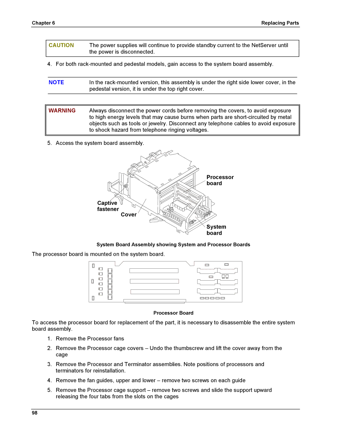
5. Access the system board assembly.
Processor board
Captive fastener
Cover
System board
System Board Assembly showing System and Processor Boards
The processor board is mounted on the system board.
Processor Board
To access the processor board for replacement of the part, it is necessary to disassemble the entire system board assembly.
1.Remove the Processor fans
2.Remove the Processor cage covers – Undo the thumbscrew and lift the cover away from the cage
3.Remove the Processor and Terminator assemblies. Note positions of processors and terminators for reinstallation.
4.Remove the fan guides, upper and lower – remove two screws on each guide
5.Remove the Processor cage support – remove two screws and slide the support upward releasing the four tabs from the slots on the cages
98