Online Version Last Updated May
HP NetServer LH 6000/LH 6000r
Audience Assumptions
Contents
To configure the drives in the hot-swap cage as a RAID array
Replacing Parts
105
General Information
Removing Covers Pedestal LH6000
Unlock the bezel Pull bezel toward you, then
Removing Covers Rack Mount LH6000r
Thumbscrew
Leveler Feet Anti-Tip Foot
Top Cover Bottom Cover
Top Cover
Removing the System Board Assembly
Page
Front View
Front of LH6000r Chassis
Front of LH6000 Chassis
Lights and Indicators
Rear View
Front Panel Console Switch and Indicator Descriptions
Indicators and Controls behind the LH 6000r Front Bezel
Hard Disk Drive LED Indicators
PCI Power LEDs Internal
LEDs at the Rear of the Chassis
Status LED Condition
PCI Attention LEDs
Power Supply LEDs
Main Menu
Green LED Indicates this HP NetServer Status
LAN LEDs
Event Log Menu
Viewing System Information
Front Panel Console Buttons Button Name Description
Chapter General Information
Boot Priority
IRQ Settings
Connector Pinouts
Video Connector Pinouts
Serial Port Connector
Video Connector Pinouts Pin Number Function
Serial Port Connector Pinouts Pin Number Signal Description
Parallel Port Connector
Pin Narrow Scsi Port Connector
Mini-DIN Connectors
Pin Number Signal Description
LAN Connector Pin Number Signal Description
Memory Guidelines
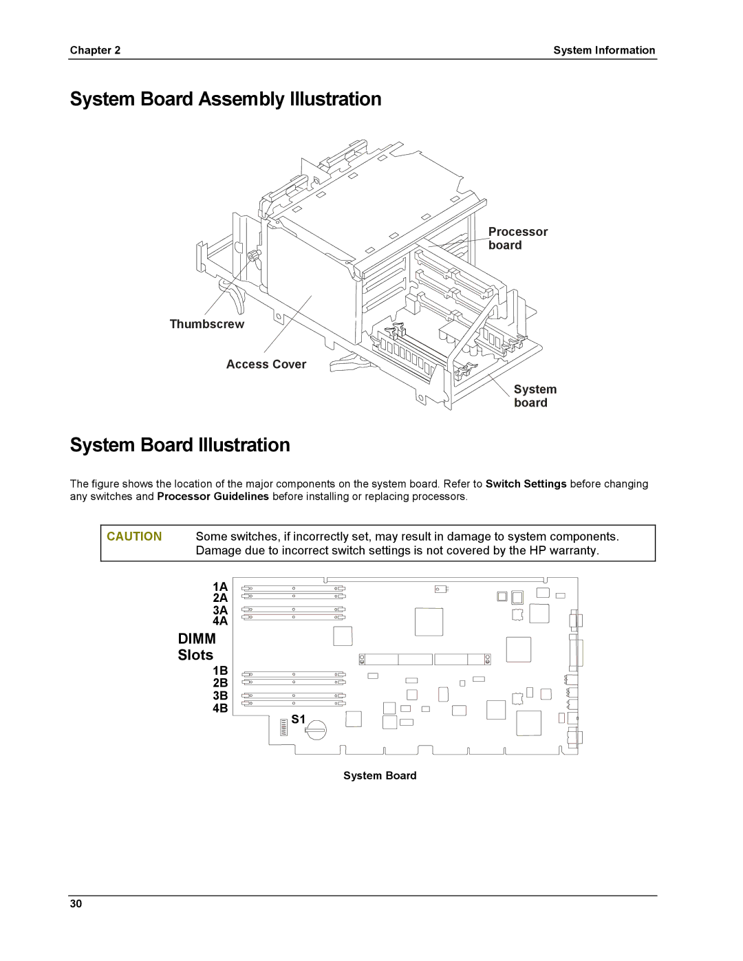
Slots
1B 2B 3B 4B
Mass Storage Guidelines
Accessory Board Guidelines
Hot Addition and Replacement of Hot Plug PCI Boards
Location Drive Type
Remote Control Top Tools Board
Online Replacement, Hot Swapping, of a PCI Adapter
To disable Scsi a channel
HP NetRAID Guidelines
Configuration Switches S1-S4 CPU Speed
Processors Guidelines
Technical Specification
Resolution Color Depths
Video
3D Video Modes
Environment Specifications
Dimensions
Switch Settings
Power Requirements
Configuration Switches S5-S8 Function To Enable
System Board Assembly Illustration
System Board Illustration
Power LEDs Attention LEDs
Board Illustration
Remote Memory SE Scsi Management Slots 1 Non-hot-plug +5V
Slots 5 Hot-plug Slots 7 +3.3V or +5V
Power Management/Interconnect Board Illustration
Parts Information
Exploded View Covers, Bezel, Front Panel
Exploded View Power Supply, I/O Board, Fans
Exploded View Mass Storage
Exploded View System Board Assembly
Exploded View Exhaust Fans
Replaceable Parts List
Description Replacement Exchange
Description Replacement Exchange
Dimm 128MB Sdram
Power Cords
Cabling Diagram
Keyboards
Cabling Power
HP NetServer LH6000/LH6000r Cabling Data
Diagnostic Tests
Diagnostics Description
HP NetServer DiagTools
DiagTools Capabilities
About Error Messages
Advantages and Limitations of Hardware Diagnostics
Post Routines
Beep Codes
Error Messages
Beep Code Test Failure Port 80H Repair
If you still dont see anything
An ISA accessory board reports an initialization problem
HP NetServer Management Controller failed its self-test
Keyboard has reported an error during its self-test
Mouse has reported an error during its self-test
Dimm Management Controller has failed to respond
Keyboard is not connected
CD-ROM drive has reported an error during its self-test
Chapter Diagnostics
Integrated LAN interface is not responding
Chapter Diagnostics
Preventive Maintenance Procedures
Troubleshooting Tips
Component Time Frame Maintenance Procedure
General Troubleshooting Sequence
Clearing the System Configuration
System Will Not Power Up
System Will Not Boot
Intermittent Failures
System Board Assembly and Configuration Switch
Password Problems
Incorrect System Configuration
Bios Recovery
Troubleshooting Checklist
Check for any general problems
General System Problems
No lights are on and no error message appears
Power goes off on the server and doesnt come back on
Server powers-off then powers on again by itself
System does not start boot
Server stops working hangs
Memory Problems
CD-ROM Problems
Symptoms CD-ROM drawer will not open
CD-ROM drive is not working properly
Flexible Disk Drive Problems
NetServer wont boot from the CD-ROM
Keyboard and Mouse Problems
Network Interface Card Problems
Symptoms Adapter cant connect to the network
Mouse does not work or is intermittent
Power Problems
Symptoms Fan is not working Power LED does not light
Scsi Subsystem Problems
Scsi Bios has trouble loading
Scsi subsystem does not work at installation
Chapter Troubleshooting
Channel x, Scsi ID #n id info Drive C 80h
Video/Monitor Problems
Scsi subsystem stops working
Chapter Troubleshooting
Configuration Problems
Symptoms An installed driver cannot find a PCI board
Configuration cannot be saved and the battery loses power
Status LED Indicator Activity LED
Verifying Hard Disk Drive Operation
Processor Problems
Light Pipes
Printer/DataComm Problems
Safety Information
Service Tools Required
Replacing Power Supply Modules
Rack version similar Power Supply Modules Thumbscrews
Replacing the Control Panel
Replacing the HP NetRAID Dimm
Replacing the System Battery
Dimm
Chapter Replacing Parts
Replacing the NetRAID Battery Backup Module Optional
System Backplane Unplug cable Battery Backup Module BBM
Replacing System Memory
System Board Assembly on Grounded Anti-static pad
Paired Memory Slots
If the latches do not close, repeat until they do
Replacing a Processor
Processor 5 6 2 VRM12 Locations
Replacing a VRM
VRM
Replacing the Power Supply Fans
Replacing the Rear Chassis Fans
Replacing the I/O Fans
Replacing the Processor Fans
Removing a Processor Fan
Replacing the Hot Swap Mass Storage Cage
Replacing the I/O Board
Raise retainer latches Disconnecting the I/O Board
Replacing the Processor Board
Processor board Captive fastener Cover System board
Replacing the System Board
100
Replacing the Power Management/Interconnect Board
102
Replacing the PCI Hot-Swap Assembly
Chapter Replacing Parts 104
DC Power Switch, 11 depth
Index
Fans
HP NetServer Assistant
Secure Mode Indicator, 11 serial port
TopTools
Troubleshooting