DW6000 specifications
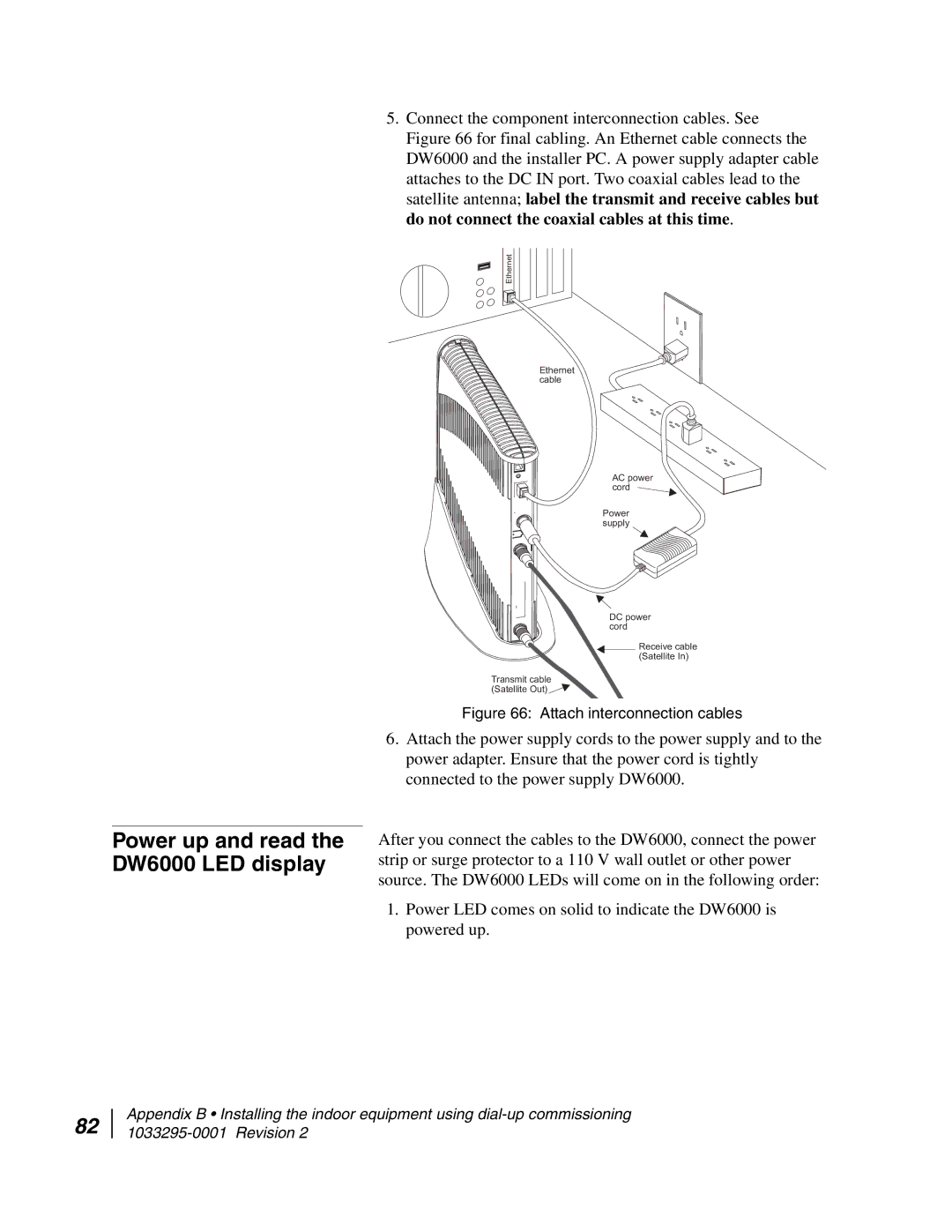
The Hughes DW6000 is a high-performance satellite modem designed primarily for broadband Internet access, particularly in remote and rural areas where traditional wired options aren’t feasible. This equipment is prominent within Hughes Network Systems' lineup of satellite communication technologies and offers a robust solution for both residential and commercial applications.One of the standout features of the Hughes DW6000 is its compatibility with the HughesNet satellite broadband service. It supports two-way satellite Internet connectivity, allowing users to send and receive data simultaneously, which enhances Internet speed and efficiency. The modem operates on the Ka-band, which is known for providing higher bandwidth and faster data transmission rates compared to traditional Ku-band systems.
The DW6000 is equipped with advanced technologies such as Adaptive Coding and Modulation (ACM), which dynamically adjusts data transmission rates based on network conditions. This feature ensures optimal performance and availability of service, even under less-than-ideal weather conditions or during peak usage times. Additionally, it includes built-in Quality of Service (QoS) capabilities, which prioritize network traffic to maintain steady, reliable performance for applications like video streaming and VoIP.
With a user-friendly design, the Hughes DW6000 offers straightforward installation and setup processes, making it accessible for users who may not have technical expertise. Its compact size also allows for easy placement in various environments.
Moreover, the modem supports various interface options, including Ethernet for connecting multiple devices, and USB connections for individual setups. This versatility makes it a fit for both home networks and small office environments.
The DW6000 also has security features in place, including encryption options to safeguard data transmission. This is particularly important in today's digital landscape, where data privacy and security are vital considerations.
In summary, the Hughes DW6000 satellite modem stands out for its robust features, including support for high-speed Internet access, dynamic transmission adjustments through ACM, and user-friendly installation. Its versatility, combined with essential security measures, makes it a solid choice for anyone looking to establish reliable connectivity in hard-to-reach locations. Whether for home use or business applications, the DW6000 delivers the performance needed to keep users connected in an increasingly digital world.

