2142 2140
Page
2142 2140
Such
1998
Contents
Parts/Test
Index
Safety
FRU Part
Page
Vii
Voltage Supply Switch Settings
IBM
Viii
Positionnement du sélecteur de tension
Safety Information
Safety Notices Multi-Lingual Translations
Pilha
Xii
Safety Notice
Xiv
Statement
Laser
Laser
El uso
Aquí
Peligrosas
Xvi
Federal Communications Commission FCC Statement
Federal Communications Commission FCC Notice
Xviii
Canadian Department of Communications Compliance Statement
Canadian Department of Communications Certification Label
Avis
Dhomologation du ministère des Communications du
Canada
Intégré Est
Trademarks
Xxii
Parts/Test Point
Model/Monitor Configurations and FRU Part
Information
Repair
Xxiv
Parts Catalog
Beeps
Diagnostic Information
Chapter Description
Start
Using
Diagnostic Aids
Parts Catalog
Safety Inspection Guide
Repair Information
Point Locations
Appendix Model Configurations and FRU Part Numbers
Vesa
Product Description
PCI/ISA
Sdram
Processors
IDE/AT
Features
FST
FST CRT
OSD
Keyboard
Hardware Interfaces
Hardware Interfaces
Refresh Rates and Monitor Frequencies-Type A-1
Monitor Frequencies
Refresh Rates
Power-On
Reset
Enabled . If
Flash Bios Update Procedure
DIN
Bios
Bios Setting
Card
Zero
CD\DISK\CRYSTAL\CLYDE\RCAND15\INSTALL\DISK0
23AXXXX
Updating Amplifier
Utility
Setup Utility
Using the Setup Utility
Starting
Down
KeysFunction
Utility
Setup
Ports
Play
This Screen provides Model Number, serial
PCI
Using Power Management Utilities
Power Management Utility Features
SelectAccess Aptiva SelectControl
Power Management Utility Normal Operation
Post
Error
Dimm
System Memory
Dimm Identification
Specifications
High Range
Low Range
Special Tools
Operating Requirements
Check Procedures
Start
001
002
Does
ON?
Do ANY MESSAGES, Error CODES, or Symptoms APPEAR?
010
007
Did the System Produce the Readable SCREEN?
Yes No 009
CODES?
Identify
UNIT?
Test Diagnostics
Beeps
Symptoms, Messages
Index
If you
Beeps
Error Action/FRU
Post and Diagnostics and Utilities Index
Messages, Error
Error
Messages, Error
CPU
IRQ
Selected Printer Ensure
CD/DVD-ROM Drive or Diskette Drive
COM
Messages, Error Action/FRU
Address Exceeds
Cannot
Bios
ROM
Board Parity
Page
6XX
PCI
ISA
1804
5886 Pointing Device Check Cable Attached Media
Yes 005
Power Supply
FAN
Yes 002
Hard Drive or CD/DVD-ROM End of Power Cable
ON/OFF
Are
FAN RUN?
Unit
YOU
ERROR?
Memory
Did
008
Or a
Did the Symptom REMAIN?
Keyboard
Yes No
Post
Did the Symptom CHANGE?
Are the Voltages CORRECT?
Mouse
Did the System Produce the Main Menu SCREEN?
Diagnostics and Utilities Device Presence Test
Do ANY MESSAGES, Error CODES, BEEPS, or Symptoms APPEAR?
Config
Yes 009
Yes 007
Layout-Type 5-2, System Board Run theEasy
Console Drive
List Not
Factory-Installed Drive Devices
Run
Zip Drive
Did ANY Tests FAIL?
33.6
Adapters
Kbps
WHEN-WAKE UP the Computer
Feature is
ENABLED?
Fail
Yes No 010 Replace System Board 011
Yes No 004
Monitor
SCREEN?
Did the Display SELF-TEST Pattern Remain on the Screen
SelectInteractive Tests
SelectDiagnostics
ALL TESTS?
History
Problem
Device With its own Not supported
Processor Removed Step
Diagnostic Aids
Xxxxxx
Power-On Self Test
Introduction
VGA
To load
Utilities
Utilities
Utilities
Creating a Diagnostics Bootable Diskette
To create a bootable diagnostics diskette
To Load the Diagnostics Diskette
If any Post errors appear After
Feature
Diagnostic Test Programs
Description
Error Messages
Keys
Using the Advanced Diagnostic Test Programs
Using First Letter
Program Navigation
CD/DVD-ROM
Command Line Options
Nomouse
Hard Disk Drive Boot Error
Editor from
File Editor
Ascii
Display Self Test
Off
Display Under Power Management
Page
Repair Information
Removals and Replacements-Machine Type 2140
Service Panel
Cover
5-In., 5.25-In. Cage
2020-3.5-In., 5.25-In. Cage
5-In. Cage
Console back cover removal
Media Console
JP7 JP6 JP4
Console left and right side covers
Removing the console
Removing the console bottom plate Console spring
Power Supply
11. Memory Dimm
Memory Dimm
See Safety Notice 2 Translation on
Lithium Battery
System Board
Handling ESD-Sensitive Parts
How Home Director Works
Home Director Technical Service and Support
Home Director
Do not
Home Director Troubleshooting
HOM
Software Installation Procedure
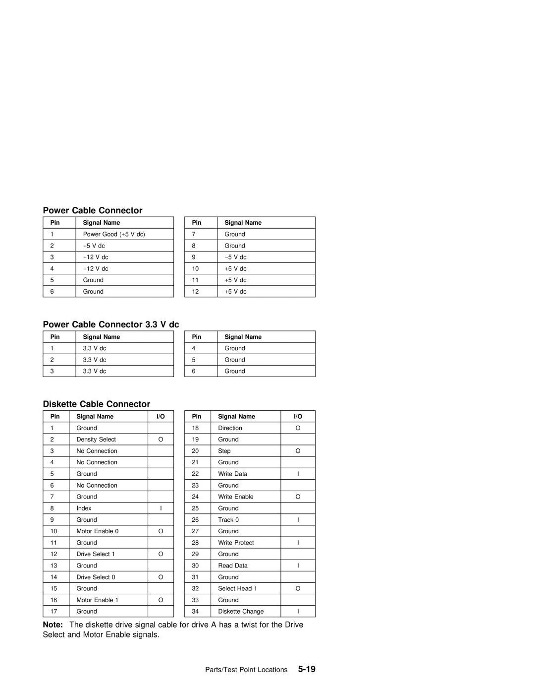
Locations
Parts/Test
JP4
System Board Layout-Type A-1
JP2
JP5
Board Locations-Type
System
MMX
Pentium
J6A,B,C
JP1
DIMM1 J1A KSLOTA1 DIMM2 DIMM3 J1B
J8A
J1A/J1B
System Board
Bus
Factory-Installed Modem Card
Kbps Modem
IDE
Hard Disk Drive Jumper Settings
Disk Drive
IDE Local
Maxtor Hard Disk Drives
Quantum Hard Disk Drives
11. CD/DVD-ROM Drive Jumper Settings
CD/DVD-ROM Drive Jumper Settings
Zip Drive
12. Zip Drive Jumper Settings
Detachable Monitor I/O Signal Cable Connector Test Points
Media Console Cable
Pin Signal
Parallel Port
System Board Connector Specifications
Monitor/Signal
Serial Port
Power Management Power
On/Off Switch Connector
Connector
Diskette
Power Cable Connector 3.3 V dc
Disk Cable
Hard
Inspection
Guide
Page
Similar
How to Use This Parts Catalog
Assemblies Service Level a
ZIP
Asm Part Index
Assembly 2 Machine Type 2140 System Unit Interior SL-A
Dimm Sdram
All System
Are Shipped
Assembly
Description
Assembly 3 Machine Type 2142 System Unit Exterior SL-A
Assembly 4 Machine Type 2142 System Unit Interior SL-A
OUT
All
12J5962
Assembly 5 Diskette, Hard Disk Drives, and Zip Drive
75H9550
Assembly 6 Media Console Type
12J5835
Assembly 7 CD/DVD-ROM Drive, Modem, and TV Cards
AUS DEN, SWE, NOR, FIN, SWI
FR, GR
60H6045
Inch Monitor MM55 Type
Assembly 8 Monitor and Power Cord Linecord
Inch Monitor MM75 Type
Power Cord linecord For monitor and system unit
EZ Button
Assembly 9 Keyboard and Mouse
12J5642 English 12J5607
Assembly 10 Software
Part Asm
Part
Number Index
Part Asm Number Index
Page
Bit Parity .bit
BBS
IBM PC
Connection
Appendix B. Model/Monitor Configurations FRU Part Numbers
U.S
Processor Memory Drive
Model Board Processor Memory Drive
Emea
Latin America Machine Type 2140 2142 Factory-Installed Parts
Table B-6. Monitor-to-FRU Index Frequency Settings
Page
Numerics
USB
MMX
Processors
Page
IBM