5.1.8 MERGE AND SPLICE ADJUSTMENT (8)
This feature lets you precisely adjust the effective camera position to eliminate discontinuities across camera boundaries. Merging is adjustment along the scan line. Splicing is adjustment perpendicular to the scan line.
______________________________________________________________________
NOTE: Focus, magnification, merge, and splice functions are intertwined. If you adjust one, you must test and, if necessary, adjust the other functions. This must be done in the following order:
1.Focus
2.Magnification
3.Merge
4.Splice
______________________________________________________________________
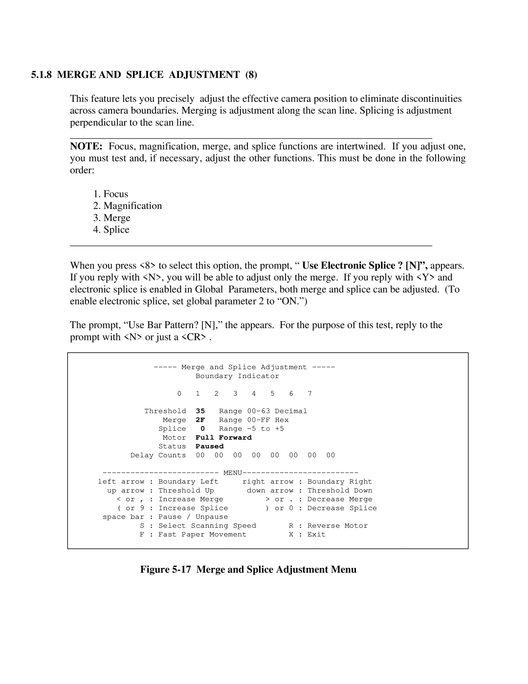
When you press <8> to select this option, the prompt, “ Use Electronic Splice ? [N]”, appears. If you reply with <N>, you will be able to adjust only the merge. If you reply with <Y> and electronic splice is enabled in Global Parameters, both merge and splice can be adjusted. (To enable electronic splice, set global parameter 2 to “ON.”)
The prompt, “Use Bar Pattern? [N],” the appears. For the purpose of this test, reply to the prompt with <N> or just a <CR> .
| and Splice Adjustment | |||||||
|
| Boundary Indicator |
|
| ||||
| 0 | 1 | 2 | 3 | 4 | 5 | 6 | 7 |
Threshold | 35 | Range |
| |||||
| Merge | 2F | Range |
|
| |||
| Splice | 0 | Range |
|
| |||
| Motor | Full Forward |
|
|
| |||
| Status | Paused |
|
|
|
|
| |
Delay | Counts | 00 | 00 | 00 | 00 | 00 | 00 | 00 00 |
left arrow : Boundary Left |
| right arrow : Boundary Right | ||||||
up arrow : Threshold Up |
| down arrow : Threshold Down | ||||||
< or , : Increase Merge |
|
| > or | . : Decrease Merge | ||||
( or 9 : Increase Splice |
|
| ) or | 0 : Decrease Splice | ||||
space bar : Pause / Unpause |
|
|
|
|
| |||
S : Select Scanning Speed |
| R : Reverse Motor | ||||||
F : Fast Paper | Movement |
| X : Exit | |||||
|
|
|
|
|
|
|
|
|