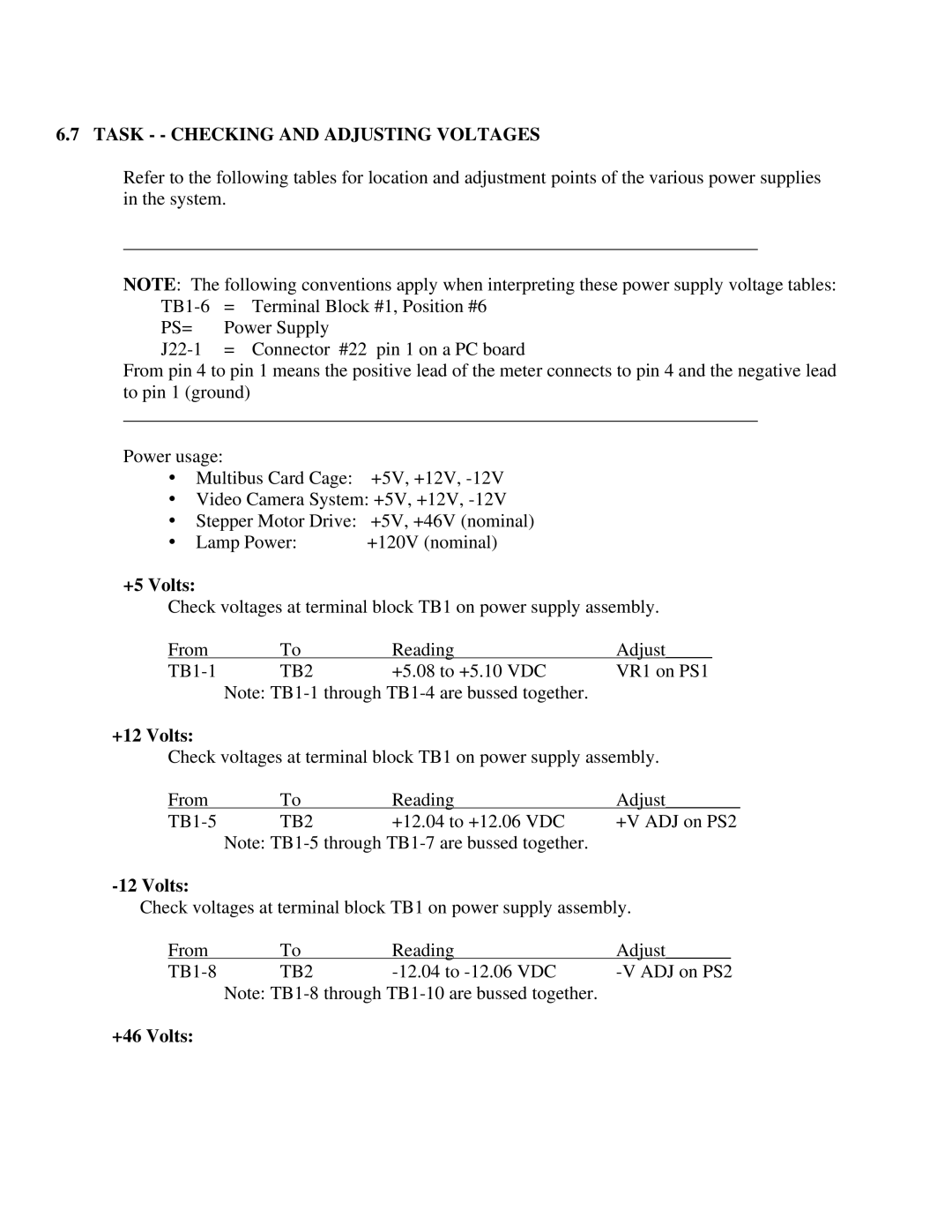
6.7 TASK - - CHECKING AND ADJUSTING VOLTAGES
Refer to the following tables for location and adjustment points of the various power supplies in the system.
____________________________________________________________________
NOTE: The following conventions apply when interpreting these power supply voltage tables:
= | Terminal Block #1, Position #6 | ||
PS= | Power Supply |
| |
= | Connector | #22 pin 1 on a PC board | |
From pin 4 to pin 1 means the positive lead of the meter connects to pin 4 and the negative lead to pin 1 (ground)
____________________________________________________________________
Power usage:
•Multibus Card Cage: +5V, +12V,
•Video Camera System: +5V, +12V,
•Stepper Motor Drive: +5V, +46V (nominal)
• Lamp Power: | +120V (nominal) |
+5 Volts:
Check voltages at terminal block TB1 on power supply assembly.
From | To | Reading | Adjust_____ |
TB2 | +5.08 to +5.10 VDC | VR1 on PS1 | |
| Note: |
| |
+12 Volts:
Check voltages at terminal block TB1 on power supply assembly.
From | To | Reading | Adjust________ |
TB2 | +12.04 to +12.06 VDC | +V ADJ on PS2 | |
| Note: |
| |
-12 Volts:
Check voltages at terminal block TB1 on power supply assembly.
From | To | Reading | Adjust_______ |
|
TB2 | ||||
| Note: |
|
| |
