5.1.5Splice Counts (5)
The Splice Counts option provides a method to list and modify line splice settings. The counts are usually set interactively through choice 8, "Merge & Splice Adjustment," on the Diagnostic Tests menu ( see 5.1.8 ) .
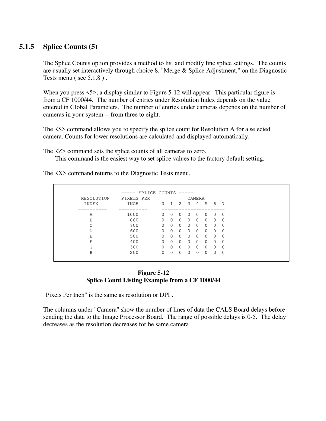
When you press <5>, a display similar to Figure
The <S> command allows you to specify the splice count for Resolution A for a selected camera. Counts for lower resolutions are calculated and displayed automatically.
The <Z> command sets the splice counts of all cameras to zero.
This command is the easiest way to set splice values to the factory default setting.
The <X> command returns to the Diagnostic Tests menu.
|
|
|
|
| |||||
RESOLUTION | PIXELS PER |
|
|
| CAMERA |
|
|
| |
INDEX | INCH | 0 | 1 | 2 | 3 | 4 | 5 | 6 | 7 |
A | 1000 | 0 | 0 | 0 | 0 | 0 | 0 | 0 | 0 |
B | 800 | 0 | 0 | 0 | 0 | 0 | 0 | 0 | 0 |
C | 700 | 0 | 0 | 0 | 0 | 0 | 0 | 0 | 0 |
D | 600 | 0 | 0 | 0 | 0 | 0 | 0 | 0 | 0 |
E | 500 | 0 | 0 | 0 | 0 | 0 | 0 | 0 | 0 |
F | 400 | 0 | 0 | 0 | 0 | 0 | 0 | 0 | 0 |
G | 300 | 0 | 0 | 0 | 0 | 0 | 0 | 0 | 0 |
H | 200 | 0 | 0 | 0 | 0 | 0 | 0 | 0 | 0 |
|
|
|
|
|
|
|
|
|
|
Figure
Splice Count Listing Example from a CF 1000/44
"Pixels Per Inch" is the same as resolution or DPI .
The columns under "Camera" show the number of lines of data the CALS Board delays before sending the data to the Image Processor Board. The range of possible delays is