■Selecting a memory channel
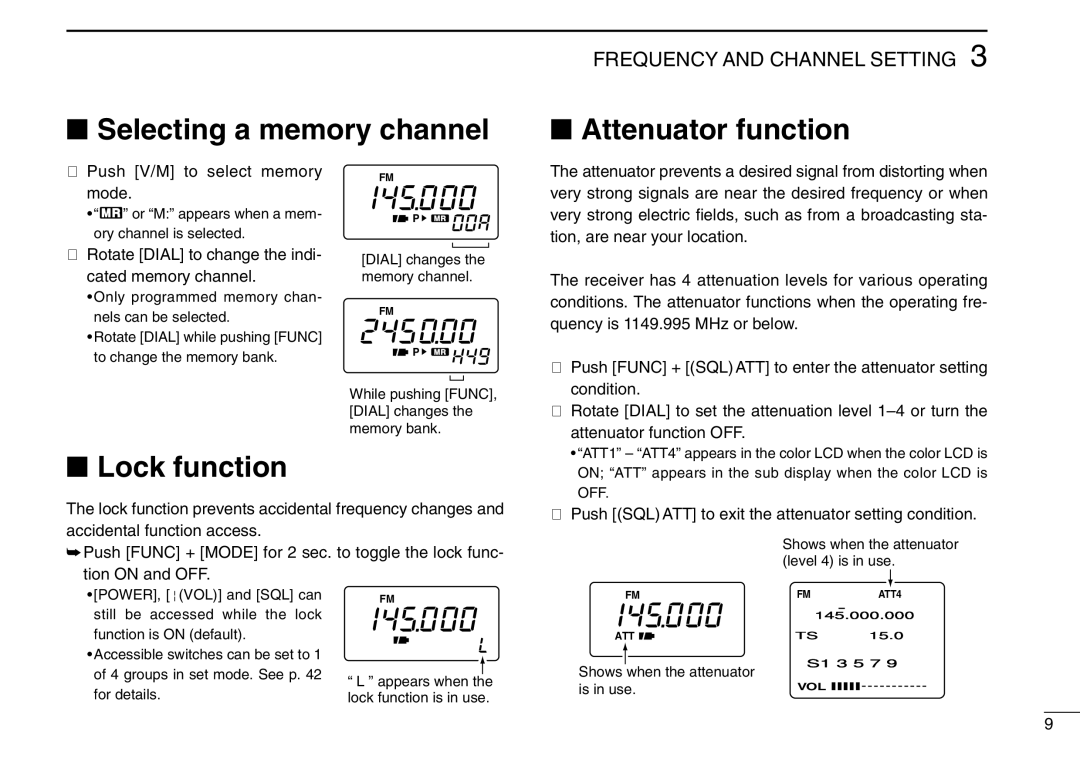
q Push [V/M] to select memory | FM | |
mode. | ||
| ||
• “X” or “M:” appears when a mem- | P | |
ory channel is selected. |
|
FREQUENCY AND CHANNEL SETTING 3
■Attenuator function
The attenuator prevents a desired signal from distorting when very strong signals are near the desired frequency or when very strong electric fields, such as from a broadcasting sta- tion, are near your location.
wRotate [DIAL] to change the indi- cated memory channel.
•Only programmed memory chan- nels can be selected.
•Rotate [DIAL] while pushing [FUNC] to change the memory bank.
[DIAL] changes the memory channel.
FM
![]() P
P ![]()
![]()
![]()
![]()
![]()
![]()
![]()
![]()
While pushing [FUNC], [DIAL] changes the memory bank.
The receiver has 4 attenuation levels for various operating conditions. The attenuator functions when the operating fre- quency is 1149.995 MHz or below.
qPush [FUNC] + [(SQL) ATT] to enter the attenuator setting condition.
w Rotate [DIAL] to set the attenuation level |
attenuator function OFF. |
• “ATT1” – “ATT4” appears in the color LCD when the color LCD is |
■Lock function
The lock function prevents accidental frequency changes and accidental function access.
➥Push [FUNC] + [MODE] for 2 sec. to toggle the lock func-
ON; “ATT” appears in the sub display when the color LCD is |
OFF. |
ePush [(SQL) ATT] to exit the attenuator setting condition.
Shows when the attenuator |
(level 4) is in use. |
tion ON and OFF.
•[POWER], [↕ (VOL)] and [SQL] can still be accessed while the lock function is ON (default).
•Accessible switches can be set to 1 of 4 groups in set mode. See p. 42 for details.
FM
“L ” appears when the lock function is in use.
FM | FM |
|
|
|
| ATT4 |
| ||
|
|
|
|
|
|
|
| ||
|
|
|
| 145.000.000 | |||||
ATT | TS |
|
|
| 15.0 |
| |||
Shows when the attenuator | S1 | 3 | 5 | 7 | 9 | ||||
|
|
|
|
|
|
|
|
| |
is in use. | VOL |
|
|
|
|
|
|
|
|
|
|
|
|
|
|
| |||
9