12 |
The circuit displayed on the center uses an external shunt resistor (~51.3 Ω) wired parallel to the input in order to measure current signals (e.g.
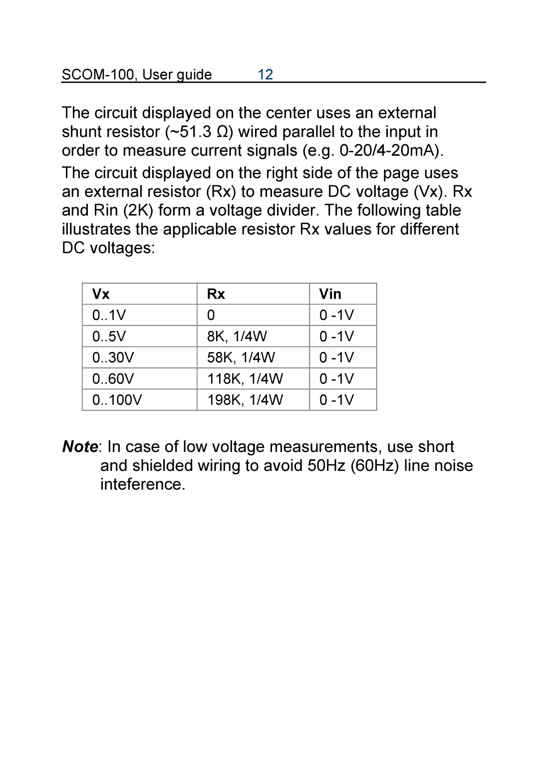
The circuit displayed on the right side of the page uses an external resistor (Rx) to measure DC voltage (Vx). Rx and Rin (2K) form a voltage divider. The following table illustrates the applicable resistor Rx values for different DC voltages:
Vx | Rx | Vin |
0..1V | 0 | 0 |
0..5V | 8K, 1/4W | 0 |
0..30V | 58K, 1/4W | 0 |
0..60V | 118K, 1/4W | 0 |
0..100V | 198K, 1/4W | 0 |
Note: In case of low voltage measurements, use short and shielded wiring to avoid 50Hz (60Hz) line noise inteference.