Page
Disclaimer
Contents
Page
Page
Connections
Device overview
LED indications
Power supply
Wiring
Digital inputs
AC1
Digital outputs
Analog input
Analog inputs
Vin
SCOM-100, User guide
Analog input
I/O expansion power supply
SCOM-100, User guide
Microphone
GSM antenna
Installing the SIM card
Getting started
Preparing a SIM card
First power up & factory settings
Device operation
SMS commands
Naming the unit
XXXX,A..A,..,..,Z..Z
1100,m,n,s,a,d
Configuring a digital input for alarming
My SCOM-100 Door contact
1100,0,1,Door contact,3,30
Setting alarm message’s texts
0630,ID,s
1101,m,n,ID1,ID2
0630,1,Door is opened 0630,2,Door is closed 1101,0,1,2,1
0630,1,Door is opened 0630,2,Door is closed
My SCOM-100 Door contact Door is opened
My SCOM-100
Clearing the digital input configuration
Door contact Door is closed
1110,m,n
Controlling the digital outputs
Setting a digital output
1000,m,n
1000,0,2
1001,0,2
Configuring an output as a closed contact
1071,m,n
1071,0,2
Pulse digital output
1070,m,n
Setting a digital output after a delay
1010,m,n,s
1010,0,2,25
1020,m,n,h,mn
Resetting a digital output after a delay
1021,m,n,h,mn
1040,m,n,mon,moff
Digital output time based scheduling
1700,ID,d,P1B-P1D,P2B-P2D,…,P8B-P8D
Time schedule program
1700,1,0,800-120,1130-1001645-180
1030,m,n,ID
1701,ID,P
Clearing the digital output configuration
1701,3,50
1090,m,n,ID
Analog signal alarming
Analog input configuration
1200,m,n,s,SSL,SSH,SCL,SCH,ALL,ALH,u,d
ALH
SCOM-100, User guide
Setting alarm message’s texts for analog inputs
1200,0,2,Pressure,819,4095,0,10000,2500 8500,mBar,15
1201,m,n,ID1,ID2
Setting the analog inputs alarm deadband
Clearing the analog input configuration
1210,m,n
1800,d
Special I/O Functions
1 ON/OFF and PID control
1250,id,m,n,m1,n1,sp,g,it,dt,ct,h
1251,id,s
1255,id,sp
1252,id,m,n
1253,id
1260,id
User administration
Create a new user
0500,id,n,p,c1,c2,c3
Defining specific alarm recipients
Change user configuration
Set a DI alarm recipient
Delete a user
Set an AI alarm recipient
Clear DI alarm recipients
Clear AI alarm recipients
Setting the device status
Device status & mode controls
RUN Control command
Monitor command
Controlling the device response
Controlling the device status
1105,m,n,v
Send acknowledgement SMS
Setting up an SMS counter
Merge concurrent alarms
Response format
Setting a GSM PIN
Setting date and time
Monitoring capabilities
Monitoring commands
5100
UNITMy SCOM-100
Using the Hyperterminal for configuration
Connecting a PC
SCOM-100, User guide
SCOM-100, User guide
Using the Scom Configurator for configuration
Ate1
Atsms=1100,0,1,Door contact,3,30
Using the microphone input
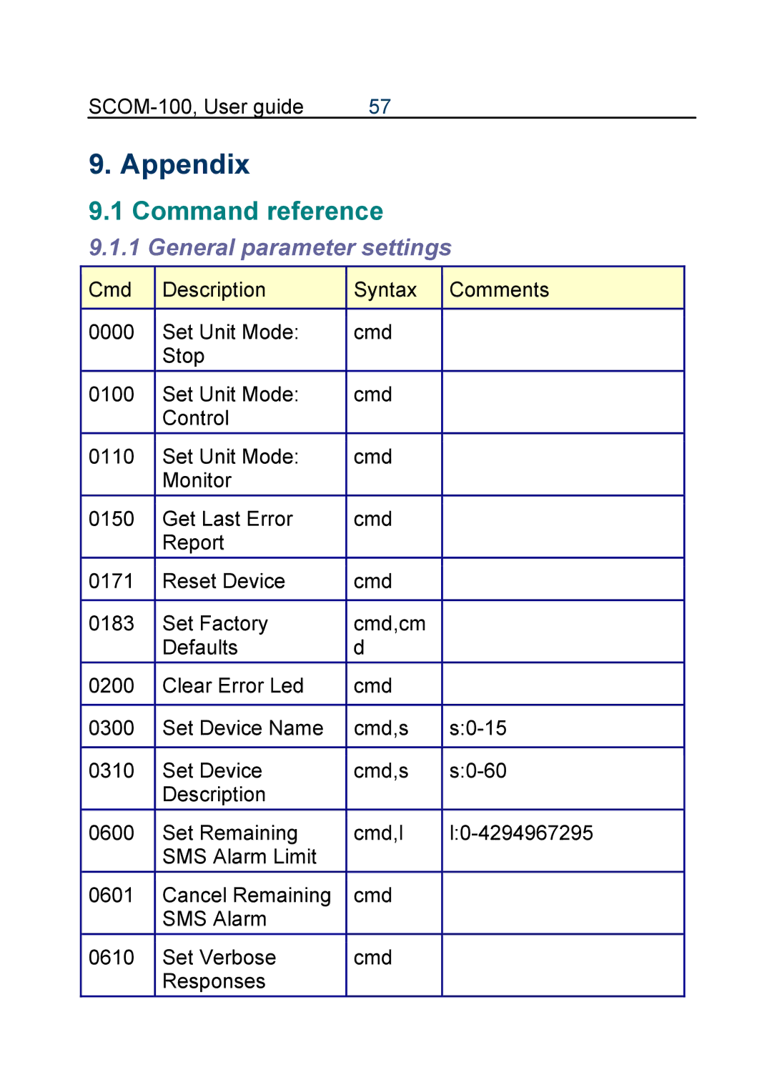
Command reference
General parameter settings
Appendix
SMS
User configuration
Output control & configuration
Input configuration
5 I/O Functions
RTC & Time scheduling
Monitoring commands
AI/DI/AO/DO
Troubleshooting
Page
Main unit
Technical specifications
GE-DIO-42 Digital I/O Expansion module
Error handling
LED
Status LED indications
GE-DIO-42 Digital I/O expansion
Default parameter values Factory settings
Setting an I/O expansion module address
Dip switch settings Module number m
PIN
RS232C connector layout