Page
Disclaimer
Contents
Page
Page
Connections
Device overview
LED indications
Power supply
Wiring
Digital inputs
AC1
Digital outputs
Analog input
Analog inputs
Vin
SCOM-100, User guide
Analog input
I/O expansion power supply
SCOM-100, User guide
Microphone
GSM antenna
Installing the SIM card
Getting started
Preparing a SIM card
First power up & factory settings
XXXX,A..A,..,..,Z..Z
SMS commands
Device operation
Naming the unit
1100,m,n,s,a,d
Configuring a digital input for alarming
My SCOM-100 Door contact
1100,0,1,Door contact,3,30
Setting alarm message’s texts
0630,ID,s
1101,m,n,ID1,ID2
My SCOM-100
0630,1,Door is opened 0630,2,Door is closed
0630,1,Door is opened 0630,2,Door is closed 1101,0,1,2,1
My SCOM-100 Door contact Door is opened
Clearing the digital input configuration
Door contact Door is closed
1110,m,n
1000,0,2
Setting a digital output
Controlling the digital outputs
1000,m,n
1071,0,2
Configuring an output as a closed contact
1001,0,2
1071,m,n
Pulse digital output
1070,m,n
Setting a digital output after a delay
1010,m,n,s
1010,0,2,25
1020,m,n,h,mn
Resetting a digital output after a delay
1021,m,n,h,mn
1040,m,n,mon,moff
Digital output time based scheduling
1700,ID,d,P1B-P1D,P2B-P2D,…,P8B-P8D
Time schedule program
1700,1,0,800-120,1130-1001645-180
1030,m,n,ID
1701,ID,P
Clearing the digital output configuration
1701,3,50
1090,m,n,ID
Analog signal alarming
Analog input configuration
1200,m,n,s,SSL,SSH,SCL,SCH,ALL,ALH,u,d
ALH
SCOM-100, User guide
Setting alarm message’s texts for analog inputs
1200,0,2,Pressure,819,4095,0,10000,2500 8500,mBar,15
1201,m,n,ID1,ID2
1800,d
Clearing the analog input configuration
Setting the analog inputs alarm deadband
1210,m,n
Special I/O Functions
1 ON/OFF and PID control
1250,id,m,n,m1,n1,sp,g,it,dt,ct,h
1251,id,s
1255,id,sp
1252,id,m,n
1253,id
1260,id
User administration
Create a new user
0500,id,n,p,c1,c2,c3
Delete a user
Change user configuration
Defining specific alarm recipients
Set a DI alarm recipient
Set an AI alarm recipient
Clear DI alarm recipients
Clear AI alarm recipients
Monitor command
Device status & mode controls
Setting the device status
RUN Control command
Send acknowledgement SMS
Controlling the device status
Controlling the device response
1105,m,n,v
Setting up an SMS counter
Merge concurrent alarms
Response format
Setting a GSM PIN
Setting date and time
UNITMy SCOM-100
Monitoring commands
Monitoring capabilities
5100
Using the Hyperterminal for configuration
Connecting a PC
SCOM-100, User guide
SCOM-100, User guide
Using the Scom Configurator for configuration
Ate1
Atsms=1100,0,1,Door contact,3,30
Using the microphone input
Command reference
General parameter settings
Appendix
SMS
User configuration
Output control & configuration
Input configuration
5 I/O Functions
RTC & Time scheduling
Monitoring commands
AI/DI/AO/DO
Troubleshooting
Page
Main unit
Technical specifications
GE-DIO-42 Digital I/O Expansion module
Error handling
LED
Status LED indications
GE-DIO-42 Digital I/O expansion
Default parameter values Factory settings
Setting an I/O expansion module address
Dip switch settings Module number m
PIN
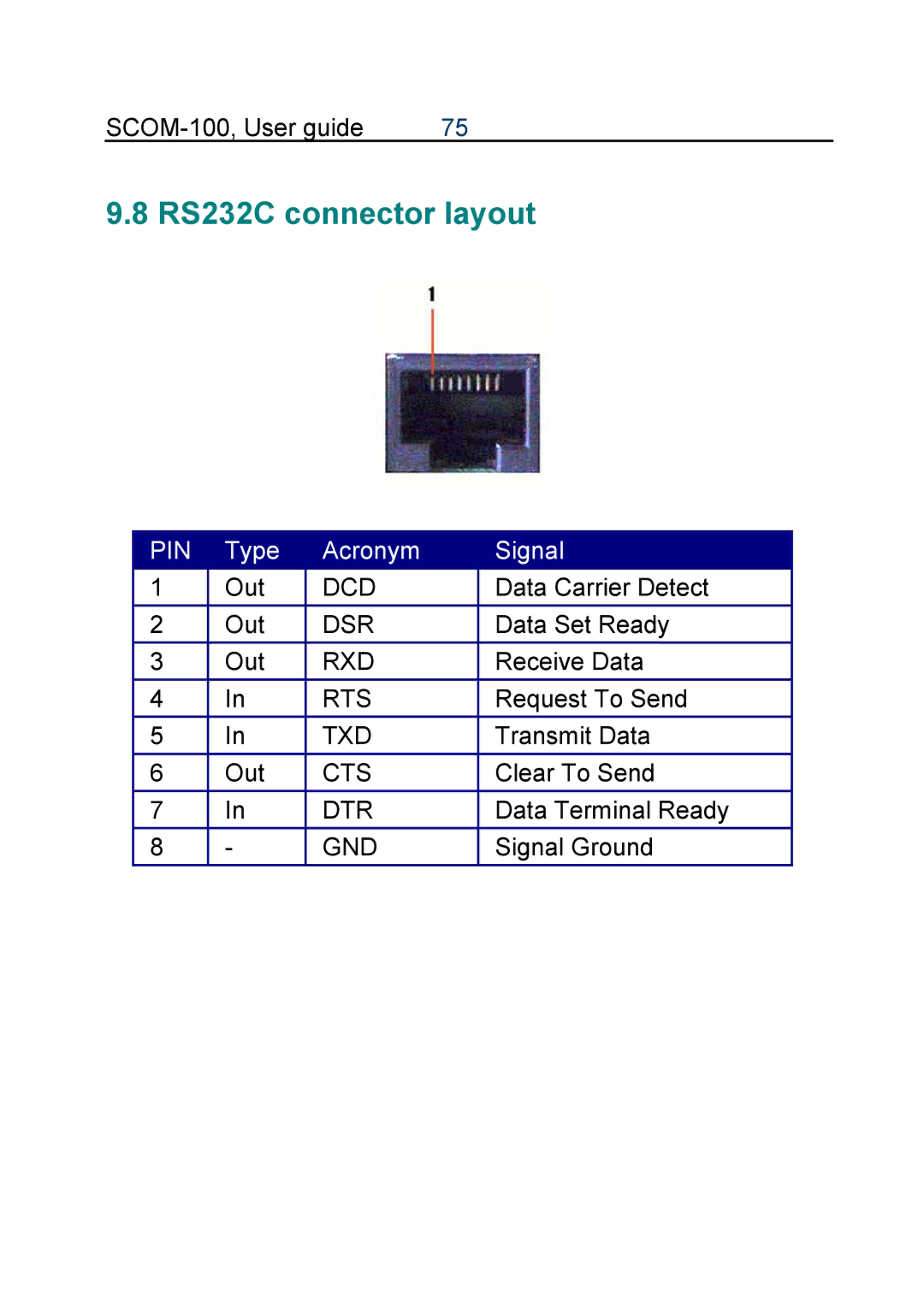
RS232C connector layout