INSTALLATION (IN-DASH MOUNTING)
The following illustration shows a typical installation. If you have any questions or require information regarding installation kits, consult your JVC
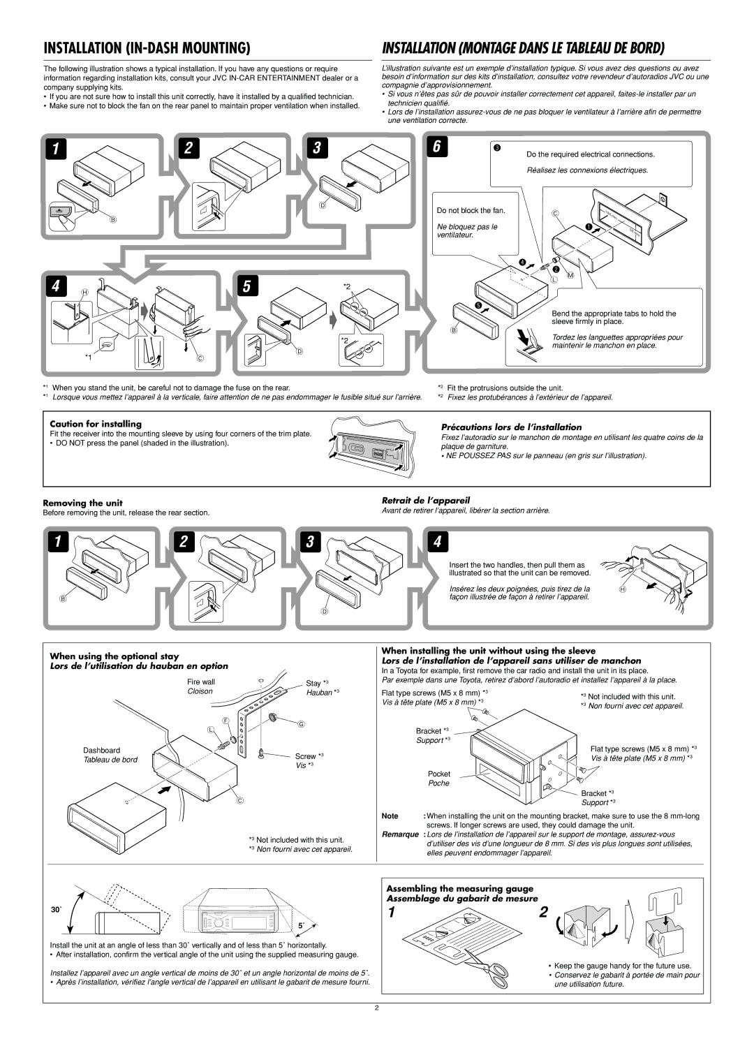
•If you are not sure how to install this unit correctly, have it installed by a qualified technician.
•Make sure not to block the fan on the rear panel to maintain proper ventilation when installed.
INSTALLATION (MONTAGE DANS LE TABLEAU DE BORD)
L’illustration suivante est un exemple d’installation typique. Si vous avez des questions ou avez besoin d’information sur des kits d’installation, consultez votre revendeur d’autoradios JVC ou une compagnie d’approvisionnement.
•Si vous n’êtes pas sûr de pouvoir installer correctement cet appareil,
•Lors de l’installation
1
23
D
6 !
Do the required electrical connections.
Réalisez les connexions électriques.
Do not block the fan. | C | 184 |
B
4 H
*1
5 | *2 |
|
*2
D
C
mm |
Ne bloquez pas le ventilateur.
@
B
~ | 53 |
|
| mm | |
|
|
⁄
![]()
![]() Ÿ
Ÿ
L M
Bend the appropriate tabs to hold the sleeve firmly in place.
Tordez les languettes appropriées pour maintenir le manchon en place.
*1 | When you stand the unit, be careful not to damage the fuse on the rear. | *2 | Fit the protrusions outside the unit. |
*1 | Lorsque vous mettez l’appareil à la verticale, faire attention de ne pas endommager le fusible situé sur l’arrière. | *2 | Fixez les protubérances à l’extérieur de l’appareil. |
Caution for installing
Fit the receiver into the mounting sleeve by using four corners of the trim plate.
• DO NOT press the panel (shaded in the illustration).
Précautions lors de l’installation
Fixez l’autoradio sur le manchon de montage en utilisant les quatre coins de la plaque de garniture.
•NE POUSSEZ PAS sur le panneau (en gris sur l’illustration).
Removing the unit
Before removing the unit, release the rear section.
Retrait de l’appareil
Avant de retirer l’appareil, libérer la section arrière.
1 | 2 | 3 | 4 |
B
D
Insert the two handles, then pull them as illustrated so that the unit can be removed.
Insérez les deux poignées, puis tirez de la | H |
façon illustrée de façon à retirer l’appareil. |
|
When using the optional stay
Lors de l’utilisation du hauban en option
Fire wall
Cloison
F
L
Dashboard
Tableau de bord
Stay *3
Hauban *3
![]() G
G
Screw *3
Vis *3
When installing the unit without using the sleeve
Lors de l’installation de l’appareil sans utiliser de manchon
In a Toyota for example, first remove the car radio and install the unit in its place.
Par exemple dans une Toyota, retirez d’abord l’autoradio et installez l’appareil à la place.
Flat type screws (M5 x 8 mm) *3 | *3 | Not included with this unit. |
Vis à tête plate (M5 x 8 mm) *3 | *3 | Non fourni avec cet appareil. |
Bracket *3 |
|
|
Support *3 |
| Flat type screws (M5 x 8 mm) *3 |
|
| |
|
| Vis à tête plate (M5 x 8 mm) *3 |
|
| |
Poche |
|
|
![]() C
C
*3 Not included with this unit.
*3 Non fourni avec cet appareil.
| Bracket *3 |
| Support *3 |
Note | : When installing the unit on the mounting bracket, make sure to use the 8 |
screws. If longer screws are used, they could damage the unit.
Remarque : Lors de l’installation de l’appareil sur le support de montage,
30˚
5˚
Install the unit at an angle of less than 30˚ vertically and of less than 5˚ horizontally.
• After installation, confirm the vertical angle of the unit using the supplied measuring gauge.
Installez l’appareil avec un angle vertical de moins de 30˚ et un angle horizontal de moins de 5˚.
• Après l’installation, vérifiez l’angle vertical de l’appareil en utilisant le gabarit de mesure fourni.
Assembling the measuring gauge
Assemblage du gabarit de mesure
12
32˚ |
|
|
28˚ | 23˚ |
|
|
| 17˚ |
|
| |
|
| 32˚ |
|
| 28˚ |
|
| 23˚ |
|
| 17˚ |
|
|
• Keep the gauge handy for the future use.
• Conservez le gabarit à portée de main pour une utilisation future.
2