Introduction
1.7 Ethernet Cable
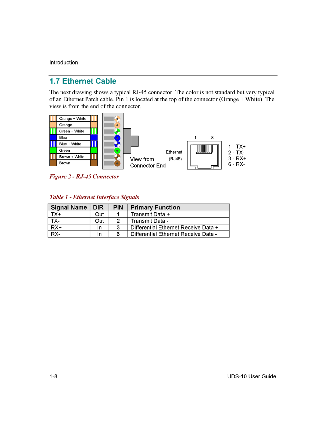
The next drawing shows a typical
Orange + White
Orange
Green + White
Blue
Blue + White
Green
Brown + White
Brown
|
|
|
|
| 1 | 8 |
|
|
|
|
|
|
| ||
|
|
|
|
|
| ||
|
|
|
|
|
| ||
|
|
|
|
|
| ||
|
|
|
|
|
| ||
|
|
|
|
|
| ||
|
|
|
|
|
| 1 | - TX+ |
|
|
|
|
|
| ||
|
|
|
|
|
| ||
|
|
|
|
| Ethernet | 2 | - TX- |
|
| View from | (RJ45) | 3 | - RX+ | ||
|
| ||||||
|
| Connector End |
| 6 | - RX- | ||
|
|
| |||||
Figure 2 - RJ-45 Connector
Table 1 - Ethernet Interface Signals
Signal Name | DIR | PIN | Primary Function |
TX+ | Out | 1 | Transmit Data + |
TX- | Out | 2 | Transmit Data - |
RX+ | In | 3 | Differential Ethernet Receive Data + |
RX- | In | 6 | Differential Ethernet Receive Data - |