UDP
8. Network Configuration using UDP
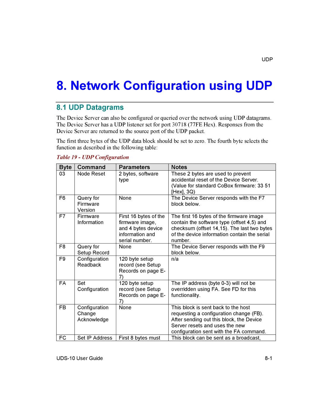
8.1 UDP Datagrams
The Device Server can also be configured or queried over the network using UDP datagrams. The Device Server has a UDP listener set for port 30718 (77FE Hex). Responses from the Device Server are returned to the source port of the UDP packet.
The first three bytes of the UDP data block should be set to zero. The fourth byte selects the function as described in the following table:
Table 19 - UDP Configuration
Byte | Command | Parameters | Notes |
03 | Node Reset | 2 bytes, software | These 2 bytes are used to prevent |
|
| type | accidental reset of the Device Server. |
|
|
| (Value for standard CoBox firmware: 33 51 |
|
|
| [Hex], 3Q) |
F6 | Query for | None | The Device Server responds with the F7 |
| Firmware |
| block below. |
| Version |
|
|
F7 | Firmware | First 16 bytes of the | The first 16 bytes of the firmware image |
| Information | firmware image, | contain the software type (offset 4,5) and |
|
| and 4 bytes device | checksum (offset 14,15). The last two bytes |
|
| information and | of the device information contain the serial |
|
| serial number. | number. |
F8 | Query for | None | The Device Server responds with the F9 |
| Setup Record |
| block below. |
F9 | Configuration | 120 byte setup | n/a |
| Readback | record (see Setup |
|
|
| Records on page E- |
|
|
| 7) |
|
FA | Set | 120 byte setup | The IP address (byte |
| Configuration | record (see Setup | overridden using FA. See FD for this |
|
| Records on page E- | functionality. |
|
| 7) |
|
FB | Configuration | None | This block is sent back to the host |
| Change |
| requesting a configuration change (FB). |
| Acknowledge |
| After sending out this block, the Device |
|
|
| Server resets and uses the new |
|
|
| configuration sent with the FA command. |
FC | Set IP Address | First 8 bytes must | This block can be sent as a broadcast, |