|
| INSTALLATION | ||||||
|
|
|
|
|
| |||
TOC | TOC | 11. Before opening the cylinder valve, turn the regula- | RECONNECT PROCEDURE |
|
|
| ||
| tor adjusting knob counter clockwise until the pres- |
|
|
|
|
| ||
|
|
|
|
|
|
|
| |
Section | Master |
| sure is released from the adjusting spring. | Multiple voltage machines are shipped connected to | ||||
|
| |||||||
|
|
|
| |||||
|
| 12. Open the cylinder valve slowly a fraction of a turn. | the highest input voltage listed on the machine's rating | |||||
|
| plate. Before installing the machine, check that the | ||||||
to | to |
|
| |||||
| a. When the cylinder pressure gage pointer stops | Reconnect Panel in the Input Box Assembly is con- | ||||||
Return | Return |
| ||||||
| nected for the proper voltage. |
|
|
| ||||
| moving, open the valve fully. |
|
|
| ||||
|
|
|
|
|
| |||
|
|
|
|
|
|
|
| |
|
|
|
|
|
|
|
| |
|
| NEVER STAND DIRECTLY IN FRONT OF OR |
| CAUTION |
|
|
| |
|
| BEHIND THE FLOW REGULATOR WHEN OPENING |
|
|
|
|
| |
|
| THE CYLINDER VALVE. ALWAYS STAND TO ONE | Failure to follow these instructions can cause immedi- | |||||
|
| SIDE. | ||||||
|
| ate failure of components within the machine. |
|
|
| |||
|
|
|
|
|
|
| ||
|
| 13. Adjust the flow regulator for the flow rate recom- | ____________________________________ |
|
| mended for the procedure and process being used | |
|
|
| |
TOC | TOC | before making the weld. | To reconnect a dual or triple voltage machine to a dif- |
| |||
| ferent voltage, change the position of the leads or links | ||
Section | Master |
| on the inside of the Case Back Reconnect Panel |
|
|
| on the Reconnect Panel based on the type of machine. |
|
|
| Follow The Input Supply Connection Diagram located |
to | to |
| Access Door. |
Return | Return |
| For codes 9402, 9723, and 10001 208/230/1/60 |
|
|
| machines, see Figure A.5. |
|
|
| For codes 9546 and 10002 230/460/575/1/60 |
|
|
| machines, see Figure A.6. |
Return to Section TOC | Return to Master TOC |
|
|
|
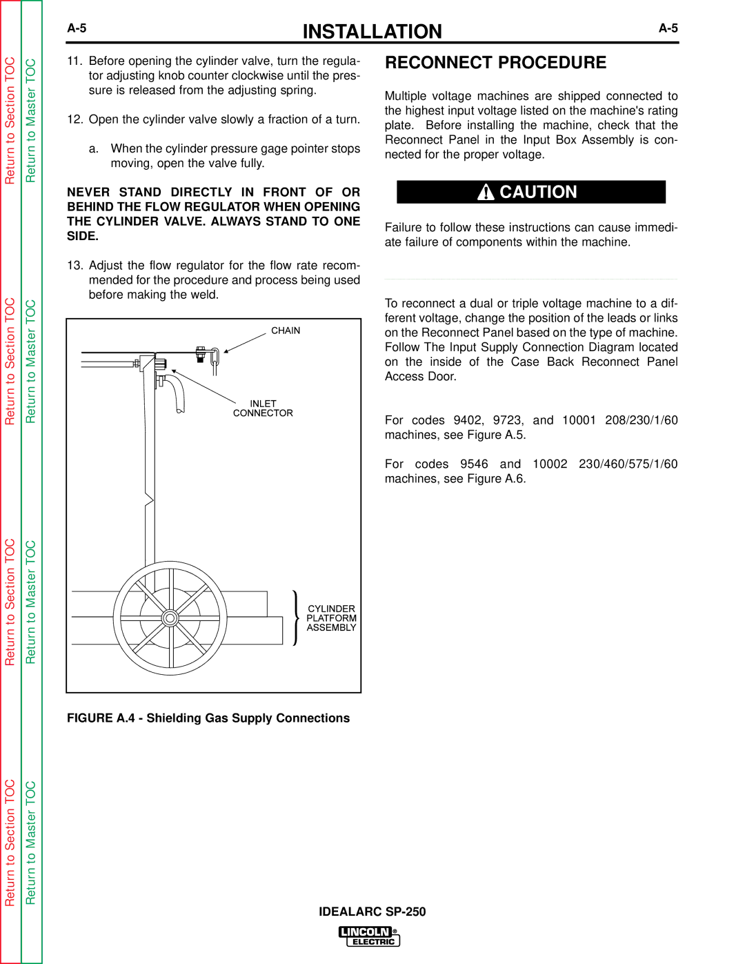
| FIGURE A.4 - Shielding Gas Supply Connections |
|
Return to Section TOC | Return to Master TOC |
| IDEALARC |
