|
|
| OPERATION | ||||
|
|
|
|
| |||
TOC | TOC | CONTROLS AND SETTINGS |
|
| |||
|
|
|
|
| |||
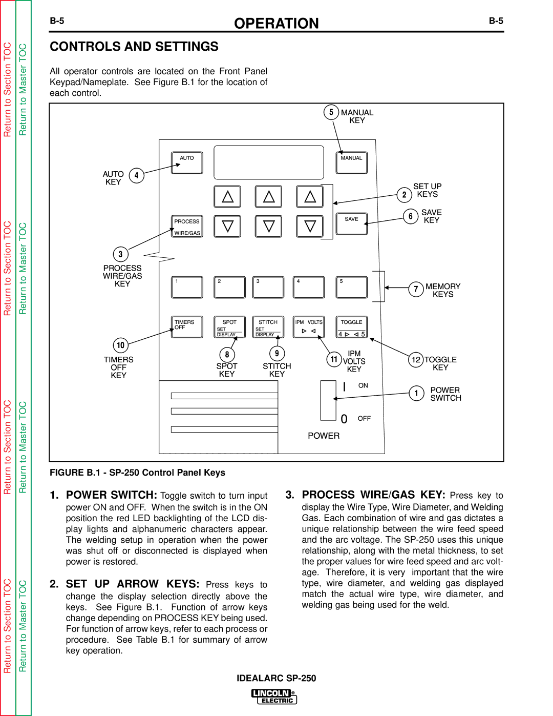
Section | Master | All operator controls are located on the Front Panel |
|
| |||
Keypad/Nameplate. See Figure B.1 for the location of |
|
| |||||
each control. |
|
|
| ||||
Return to | Return to |
|
|
| |||
|
|
|
|
| |||
Return to Section TOC | Return to Master TOC |
|
|
|
|
| |
to Section TOC | to Master TOC |
|
|
|
|
| |
Return | Return | FIGURE B.1 - |
|
| |||
1. POWER SWITCH: Toggle switch to turn input | 3. PROCESS WIRE/GAS KEY: Press key to | ||||||
|
| ||||||
|
| power ON and OFF. When the switch is in the ON | display the Wire Type, Wire Diameter, and Welding | ||||
|
| position the red LED backlighting of the LCD dis- | Gas. Each combination of wire and gas dictates a | ||||
|
| play lights and alphanumeric characters appear. | unique relationship between the wire feed speed | ||||
|
| The welding setup in operation when the power | and the arc voltage. The | ||||
|
| was shut off or disconnected is displayed when | relationship, along with the metal thickness, to set | ||||
|
| power is restored. |
| the proper values for wire feed speed and arc volt- | |||
TOC |
|
|
|
| age. Therefore, it is very | important that the wire | |
TOC | 2. SET UP ARROW KEYS: Press keys to | type, wire diameter, and welding gas displayed | |||||
change the display selection directly above the | match the actual wire type, wire diameter, and | ||||||
Section | Master | keys. | See Figure B.1. | Function of arrow keys | welding gas being used for the weld. | ||
change depending on PROCESS KEY being used. |
|
| |||||
For function of arrow keys, refer to each process or |
|
| |||||
to | to | procedure. See Table B.1 for summary of arrow |
|
| |||
Return | Return | key operation. |
|
|
| ||
|
|
|
|
| |||
