Return to Section TOC
Return to Section TOC
Return to Master TOC
Return to Master TOC
TROUBLESHOOTING & REPAIR | |
|
MAIN TRANSFORMER TEST
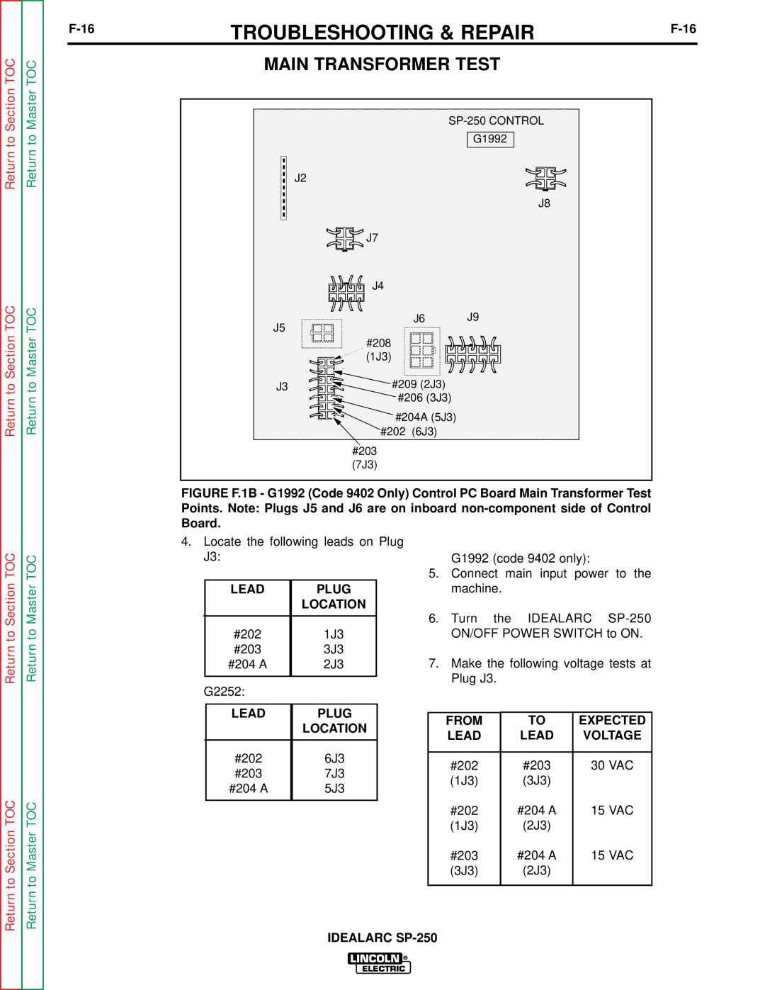
G1992
J2
J8
![]() J7
J7
J4
J6 J9
J5
#208
![]() (1J3)
(1J3)
J3 ![]()
![]()
![]()
![]() #209 (2J3)
#209 (2J3) ![]()
![]()
![]()
![]() #206 (3J3)
#206 (3J3)
#204A (5J3) #202 (6J3)
#203
(7J3)
FIGURE F.1B - G1992 (Code 9402 Only) Control PC Board Main Transformer Test Points. Note: Plugs J5 and J6 are on inboard non-component side of Control Board.
Return to Master TOC
4.Locate the following leads on Plug J3:
LEAD | PLUG |
| LOCATION |
|
|
#202 | 1J3 |
#203 | 3J3 |
#204 A | 2J3 |
|
|
G2252:
G1992 (code 9402 only):
5.Connect main input power to the machine.
6.Turn the IDEALARC
7.Make the following voltage tests at Plug J3.
Return to Master TOC
LEAD | PLUG |
| LOCATION |
|
|
#202 | 6J3 |
#203 | 7J3 |
#204 A | 5J3 |
|
|
FROM | TO | EXPECTED |
LEAD | LEAD | VOLTAGE |
|
|
|
#202 | #203 | 30 VAC |
(1J3) | (3J3) |
|
#202 | #204 A | 15 VAC |
(1J3) | (2J3) |
|
#203 | #204 A | 15 VAC |
(3J3) | (2J3) |
|
|
|
|