ACCESSORIES | ||
|
|
TOC | TOC | SPOOL GUN CONNECTION BOX | the machine connected for electrode | positive, | ||
INSTALLATION | (refer to instruction manual), remove the positive | |||||
|
| |||||
Section | Master | electrode lead from its connection on | the wire | |||
| ||||||
NOTE: Model codes below 9900 require the addition | drive. | Then reconnect with the connection box | ||||
|
| |||||
|
| electrode lead on the bolt under the positive elec- | ||||
|
| of three holes to the front of the machine's base as | ||||
to | to | trode lead so the connection box electrode lead is | ||||
shown in Fig C.3. | ||||||
sandwiched between the positive electrode lead | ||||||
Return | Return | |||||
| ||||||
| Tighten snugly, being careful not to | strip the | ||||
|
|
| terminal and the wire drive contact surface. | |||
|
|
| threads. |
| ||
Return to Section TOC | Return to Master TOC |
|
|
|
| |
|
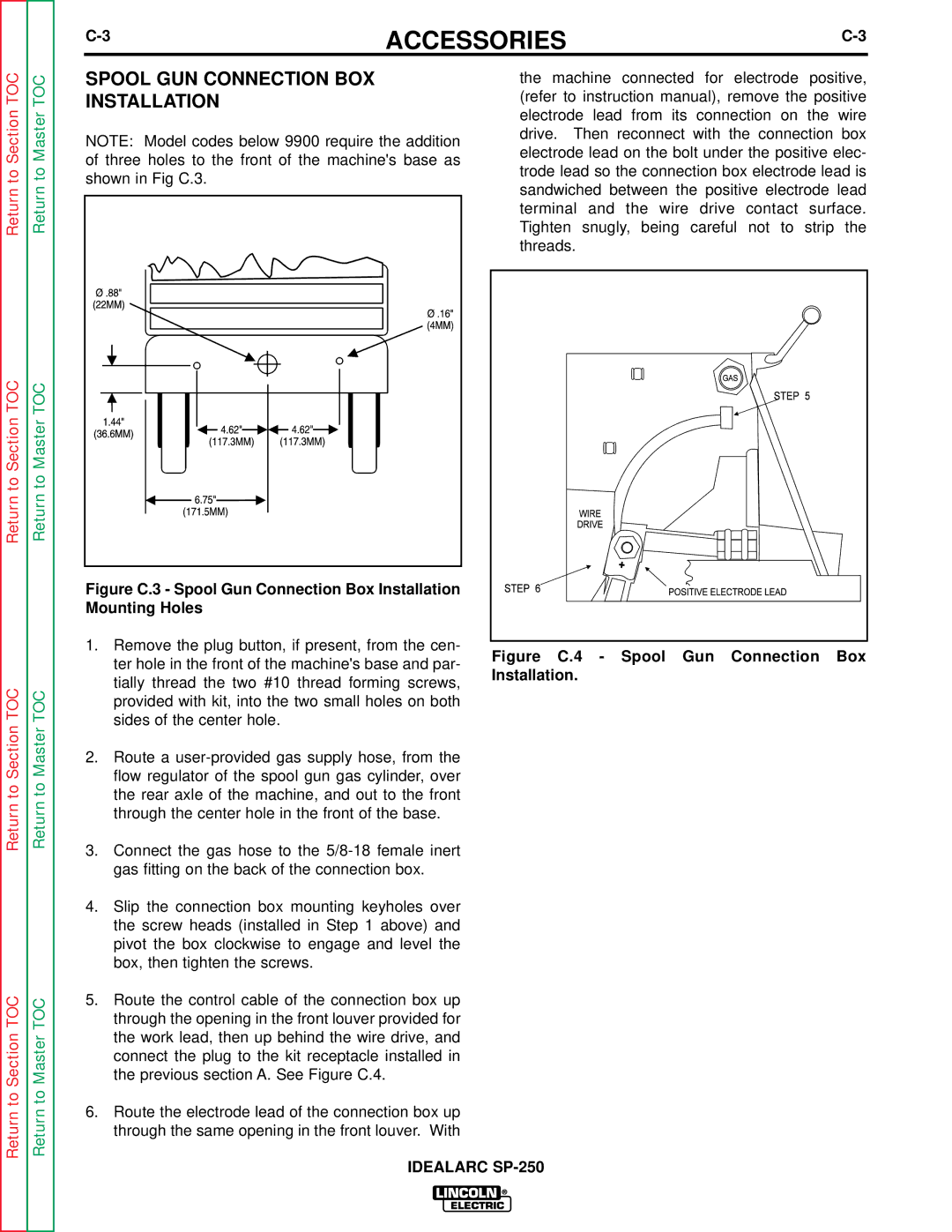
| Figure C.3 - Spool Gun Connection Box Installation |
|
|
| |
|
| Mounting Holes |
|
|
| |
|
| 1. Remove the plug button, if present, from the cen- | Figure C.4 - Spool Gun Connection Box |
|
| ter hole in the front of the machine's base and par- | |
|
| Installation. | |
|
| tially thread the two #10 thread forming screws, | |
TOC | TOC |
| |
provided with kit, into the two small holes on both |
| ||
|
|
| |
Section | Master | sides of the center hole. |
|
2. Route a |
| ||
|
|
| |
to | to | flow regulator of the spool gun gas cylinder, over |
|
the rear axle of the machine, and out to the front |
| ||
Return | Return |
| |
through the center hole in the front of the base. |
| ||
|
|
| |
|
| 3. Connect the gas hose to the |
|
|
| gas fitting on the back of the connection box. |
|
|
| 4. Slip the connection box mounting keyholes over |
|
|
| the screw heads (installed in Step 1 above) and |
|
|
| pivot the box clockwise to engage and level the |
|
|
| box, then tighten the screws. |
|
TOC | TOC | 5. Route the control cable of the connection box up |
|
through the opening in the front louver provided for |
| ||
|
|
| |
Sectionto | Masterto | the work lead, then up behind the wire drive, and |
|
connect the plug to the kit receptacle installed in |
| ||
|
|
| |
|
| the previous section A. See Figure C.4. |
|
Return | Return | 6. Route the electrode lead of the connection box up |
|
through the same opening in the front louver. With |
| ||
|
|
| |
|
| IDEALARC | |