ACCESSORIES | ||
|
|
TOC | TOC |
|
|
| CAUTION |
|
Section | Master |
|
|
|
| |
| CAUTION: Collect metal filings with a rag to protect | |||||
|
|
| ||||
to | to |
| against possible metal contamination of the control | |||
| board or other internal electrical components. | |||||
Return | Return |
| ||||
| ____________________________________ | |||||
|
|
| ||||
|
|
| 9. | Fasten the panel receptacle to the case with the | ||
|
|
|
| three | ||
|
|
|
| Insert screws from wire drive side, through the | ||
|
|
|
| sheet metal, and into the receptacle mounting | ||
|
|
|
| plate holes. |
|
|
|
|
| 10. | Plug the | ||
TOC | TOC |
|
| from the other end of the receptacle lead harness | ||
|
| into the | ||||
1. | Remove input power to the machine before start- | J13) at the top of the spool gun module board. | ||||
Section | Master | the |
| |||
|
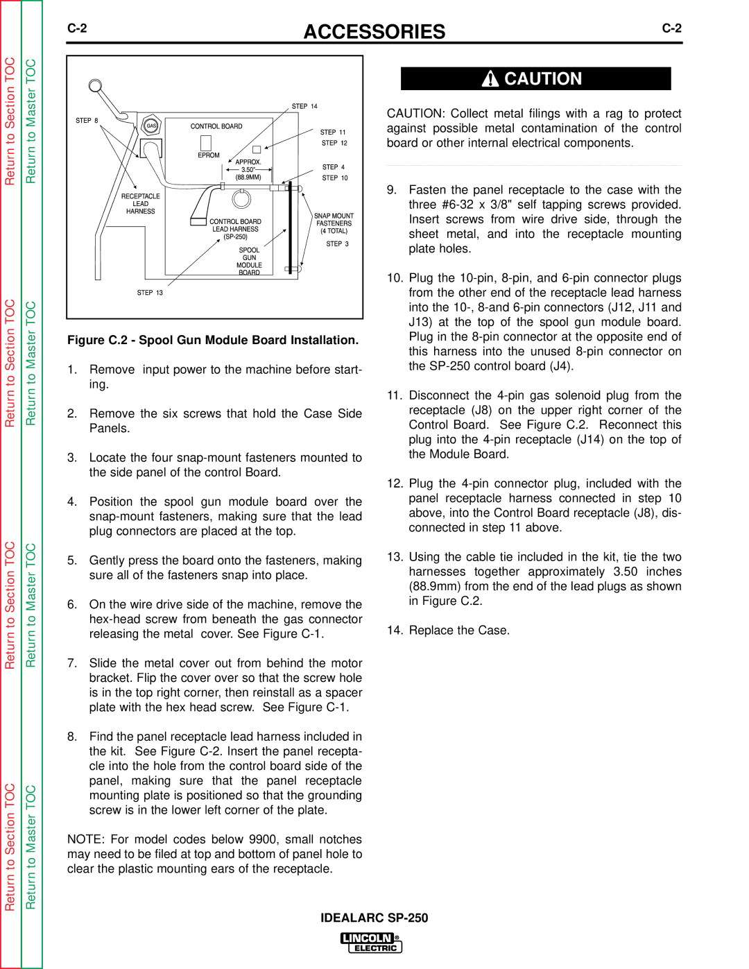
| Figure C.2 - Spool Gun Module Board Installation. | Plug in the | |||
|
|
|
| this harness into the unused | ||
to | to |
| ing. |
|
|
|
Return | Return |
|
|
|
| |
| 11. | Disconnect the | ||||
|
|
| ||||
|
| 2. Remove the six screws that hold the Case Side | receptacle (J8) on the upper right corner of the | |||
|
|
| Panels. | Control Board. | See Figure C.2. | Reconnect this |
|
|
|
| plug into the | ||
|
| 3. Locate the four | the Module Board. |
| ||
|
|
| the side panel of the control Board. | Plug the | ||
|
|
| 12. | |||
|
| 4. | Position the spool gun module board over the | panel receptacle harness connected in step 10 | ||
|
|
| above, into the Control Board receptacle (J8), dis- | |||
|
|
| plug connectors are placed at the top. | connected in step 11 above. |
| |
TOC | TOC | 5. Gently press the board onto the fasteners, making | 13. Using the cable tie included in the kit, tie the two | |
Section | Master | sure all of the fasteners snap into place. | harnesses together approximately 3.50 inches | |
| (88.9mm) from the end of the lead plugs as shown | |||
|
|
| ||
|
| 6. On the wire drive side of the machine, remove the | in Figure C.2. | |
to | to | 14. Replace the Case. | ||
releasing the metal cover. See Figure | ||||
Return | Return | |||
7. Slide the metal cover out from behind the motor |
| |||
|
| bracket. Flip the cover over so that the screw hole |
| |
|
| is in the top right corner, then reinstall as a spacer |
| |
|
| plate with the hex head screw. See Figure |
| |
|
| 8. Find the panel receptacle lead harness included in |
| |
|
| the kit. See Figure |
| |
|
| cle into the hole from the control board side of the |
| |
TOC | TOC | panel, making sure that the panel receptacle |
| |
mounting plate is positioned so that the grounding |
| |||
|
|
| ||
Section | Master | screw is in the lower left corner of the plate. |
| |
NOTE: For model codes below 9900, small notches |
| |||
|
|
| ||
to | to | may need to be filed at top and bottom of panel hole to |
| |
clear the plastic mounting ears of the receptacle. |
| |||
Return | Return |
| ||
IDEALARC | ||||
|
| |||
