Return to Master TOC
Return to Master TOC
Section
TABLE OF CONTENTS
-THEORY OF OPERATION SECTION-
Theory of Operation | Section E |
Power Supply Operation | |
Engine, Excitation, Rotor and Stator | |
Rotor Field Feedback, Auxiliary Power and Engine Idle Control | |
Auxiliary Power Overcurrent Protection | |
Weld Winding, Output Rectifier and Choke |
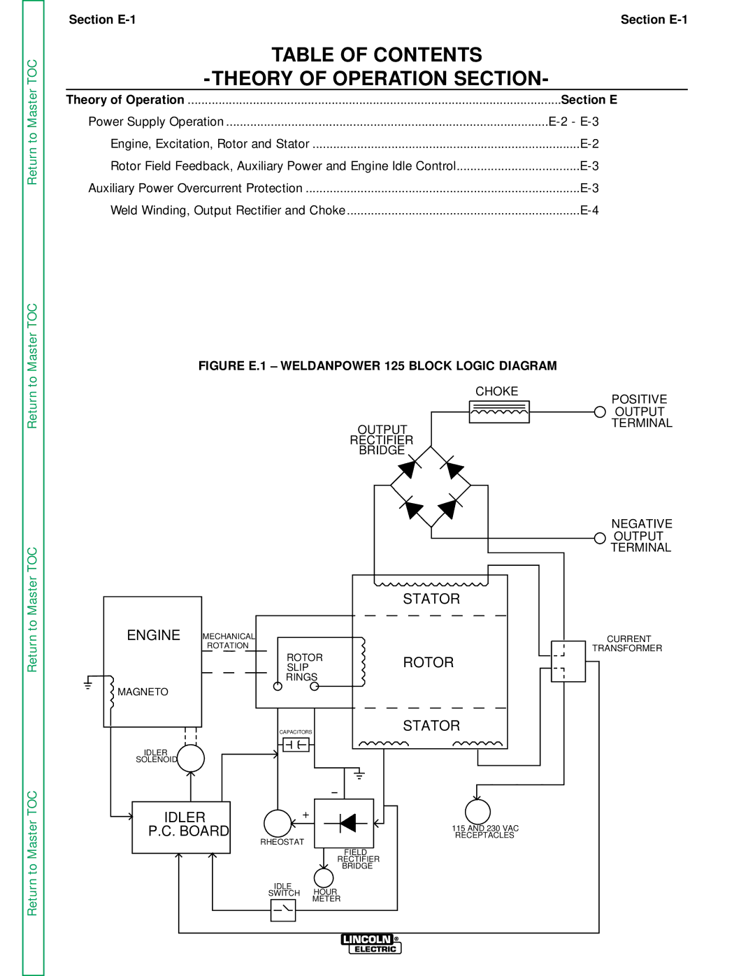
FIGURE E.1 – WELDANPOWER 125 BLOCK LOGIC DIAGRAM
| CHOKE |
| POSITIVE |
| OUTPUT |
OUTPUT | TERMINAL |
| |
RECTIFIER |
|
BRIDGE |
|
Return to Master TOC
Return to Master TOC
|
|
|
| STATOR |
ENGINE | MECHANICAL |
|
|
|
| ROTATION |
|
|
|
|
| ROTOR | ROTOR | |
|
| SLIP |
| |
|
| RINGS |
| |
MAGNETO |
|
|
|
|
|
| CAPACITORS |
| STATOR |
IDLER |
|
|
|
|
SOLENOID |
|
|
|
|
IDLER | + |
|
| |
P.C. BOARD |
|
| 115 AND 230 VAC | |
RHEOSTAT |
| RECEPTACLES | ||
|
|
|
| |
|
|
| FIELD |
|
|
|
| RECTIFIER |
|
|
|
| BRIDGE |
|
|
| IDLE | HOUR |
|
|
| SWITCH |
| |
|
|
| METER |
|
NEGATIVE OUTPUT TERMINAL
CURRENT
TRANSFORMER