Return to Section TOC
Return to Master TOC
OPERATION
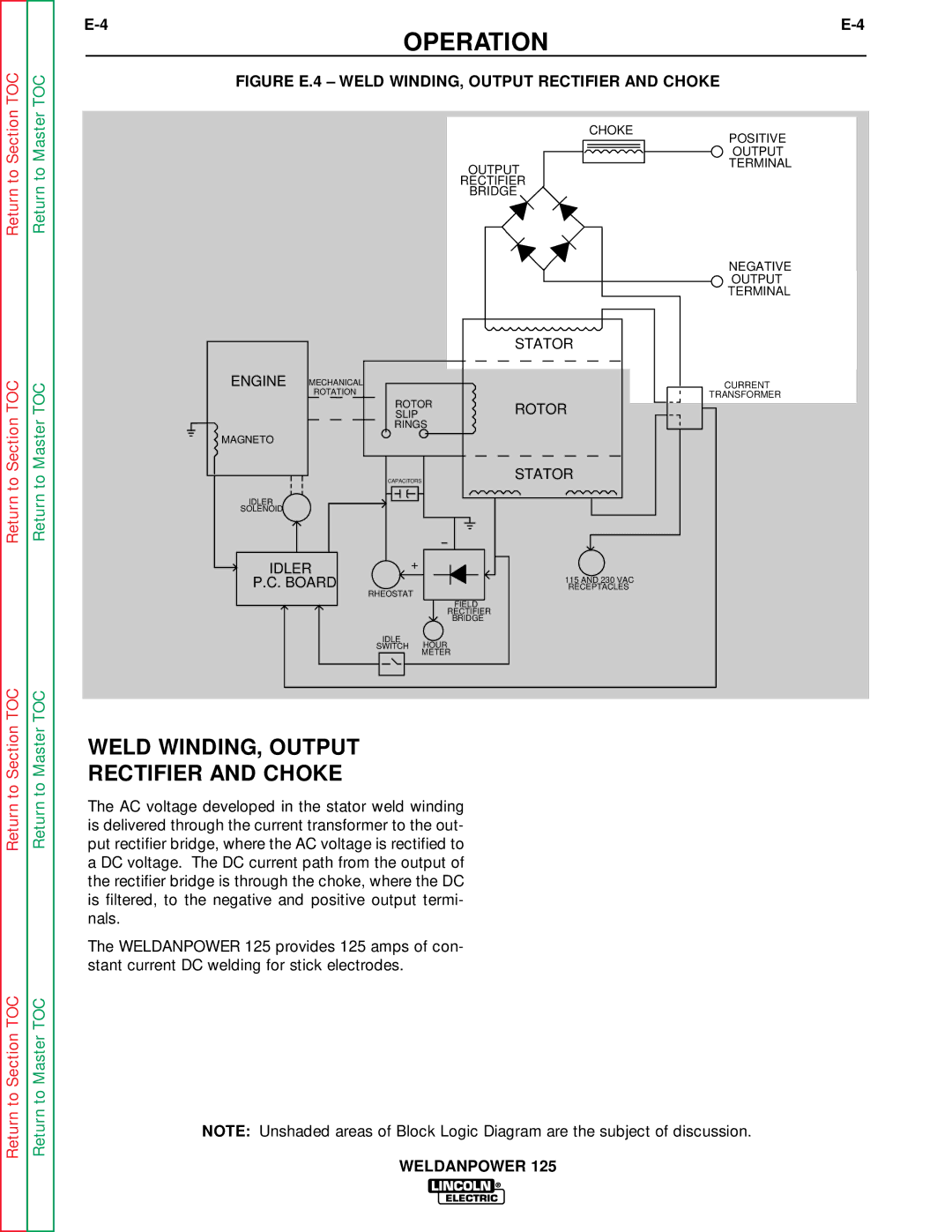
FIGURE E.4 – WELD WINDING, OUTPUT RECTIFIER AND CHOKE
| CHOKE |
| POSITIVE |
| OUTPUT |
OUTPUT | TERMINAL |
| |
RECTIFIER |
|
BRIDGE |
|
Return to Section TOC
Return to Master TOC
|
|
|
| STATOR |
ENGINE | MECHANICAL |
|
|
|
| ROTATION |
|
|
|
|
| ROTOR | ROTOR | |
|
| SLIP |
| |
|
| RINGS |
| |
MAGNETO |
|
|
|
|
|
| CAPACITORS |
| STATOR |
IDLER |
|
|
|
|
SOLENOID |
|
|
|
|
IDLER | + |
|
| |
P.C. BOARD |
|
| 115 AND 230 VAC | |
RHEOSTAT |
| RECEPTACLES | ||
|
|
|
| |
|
|
| FIELD |
|
|
|
| RECTIFIER |
|
|
|
| BRIDGE |
|
|
| IDLE | HOUR |
|
|
| SWITCH |
| |
|
|
| METER |
|
NEGATIVE
OUTPUT TERMINAL
CURRENT
TRANSFORMER
Return to Section TOC
Return to Section TOC
Return to Master TOC
Return to Master TOC
WELD WINDING, OUTPUT
RECTIFIER AND CHOKE
The AC voltage developed in the stator weld winding is delivered through the current transformer to the out- put rectifier bridge, where the AC voltage is rectified to a DC voltage. The DC current path from the output of the rectifier bridge is through the choke, where the DC is filtered, to the negative and positive output termi- nals.
The WELDANPOWER 125 provides 125 amps of con- stant current DC welding for stick electrodes.
NOTE: Unshaded areas of Block Logic Diagram are the subject of discussion.
WELDANPOWER 125