Return to Section TOC
Return to Master TOC
TROUBLESHOOTING & REPAIR
ROTOR “FLASHING” CIRCUIT TEST (continued)
FIGURE F.8 - BRUSH HOLDER LEADS 201A(-) AND 202B (+)
202B(+)
Slip
Rings
Return to Section TOC
Return to Master TOC
TEST PROCEDURE
1.With the 5/16" nut driver, remove the 8 sheet metal screws that hold the top cover to the control box. Remove the top cover.
2.Locate and remove lead #201A from the brush holder. See Figure F.8 for location.
3.Connect the negative
4.Remove lead #7A from field diode bridge rectifier D1. See Figure F.9. Electrically isolate the lead.
Return to Section TOC
Return to Master TOC
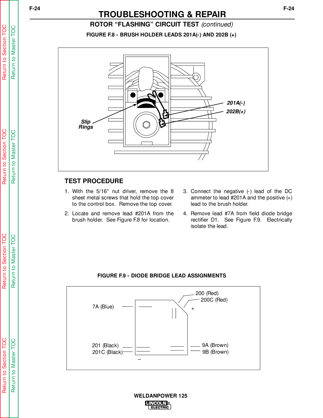
FIGURE F.9 - DIODE BRIDGE LEAD ASSIGNMENTS
Return to Section TOC
Return to Master TOC
7A (Blue)
201(Black) 201C (Black)
–
200(Red)
![]() 200C (Red)
200C (Red)
+
9A (Brown)
9B (Brown)
WELDANPOWER 125