Return to Section TOC
Return to Section TOC
Return to Master TOC
Return to Master TOC
TROUBLESHOOTING & REPAIR
STATOR/ROTOR REMOVAL AND REPLACEMENT (continued)
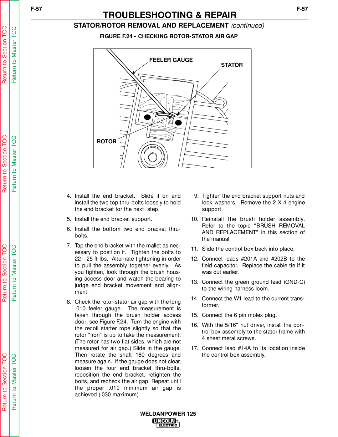
FIGURE F.24 - CHECKING ROTOR-STATOR AIR GAP
FEELER GAUGE |
STATOR |
ROTOR |
Return to Section TOC
Return to Section TOC
Return to Master TOC
Return to Master TOC
4.Install the end bracket. Slide it on and install the two top
5.Install the end bracket support.
6.Install the bottom two end bracket thru- bolts.
7.Tap the end bracket with the mallet as nec- essary to position it. Tighten the bolts to 22 - 25 ft lbs. Alternate tightening in order to pull the assembly together evenly. As you tighten, look through the brush hous- ing access door and watch the bearing to judge end bracket movement and align- ment.
8.Check the
.010 feeler gauge. The measurement is taken through the brush holder access door; see Figure F.24. Turn the engine with the recoil starter rope slightly so that the rotor "iron" is up to take the measurement. (The rotor has two flat sides, which are not measured for air gap.) Slide in the gauge. Then rotate the shaft 180 degrees and measure again. If the gauge does not clear, loosen the four end bracket
9.Tighten the end bracket support nuts and lock washers. Remove the 2 X 4 engine support.
10.Reinstall the brush holder assembly. Refer to the topic "BRUSH REMOVAL AND REPLACEMENT" in this section of the manual.
11.Slide the control box back into place.
12.Connect leads #201A and #202B to the field capacitor. Replace the cable tie if it was cut earlier.
13.Connect the green ground lead
14.Connect the W1 lead to the current trans- former.
15.Connect the 6 pin molex plug.
16.With the 5/16" nut driver, install the con- trol box assembly to the stator frame with 4 sheet metal screws.
17.Connect lead #14A to its location inside the control box assembly.
WELDANPOWER 125