Return to Section TOC
Return to Master TOC
TROUBLESHOOTING & REPAIR
IDLER PRINTED CIRCUIT BOARD REMOVAL AND REPLACEMENT (continued)
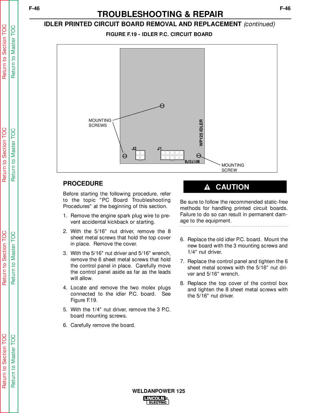
FIGURE F.19 - IDLER P.C. CIRCUIT BOARD
Return to Section TOC
Return to Master TOC
MOUNTING SCREWS
J2 | WP125 IDLER |
J1 | |
| M17578 |
MOUNTING
SCREW
Return to Section TOC
Return to Section TOC
Return to Master TOC
Return to Master TOC
PROCEDURE
Before starting the following procedure, refer to the topic "PC Board Troubleshooting Procedures" at the beginning of this section.
1.Remove the engine spark plug wire to pre- vent accidental kickback or starting.
2.With the 5/16" nut driver, remove the 8 sheet metal screws that hold the top cover in place. Remove the cover.
3.With the 5/16" nut driver and 5/16" wrench, remove the 6 sheet metal screws that hold the control panel in place. Carefully move the control panel aside as far as the leads will allow.
4.Locate and remove the two molex plugs connected to the idler P.C. board. See Figure F.19.
5.With the 1/4" nut driver, remove the 3 P.C. board mounting screws.
6.Carefully remove the board.
CAUTION
Be sure to follow the recommended
6.Replace the old idler P.C. board. Mount the new board with the 3 mounting screws and 1/4" nut driver.
7.Replace the control panel and tighten the 6 sheet metal screws with the 5/16" nut dri- ver and 5/16" wrench.
8.Replace the top cover of the control box and tighten the 8 sheet metal screws with the 5/16" nut driver.
WELDANPOWER 125