Return to Section TOC
Return to Master TOC
OPERATION
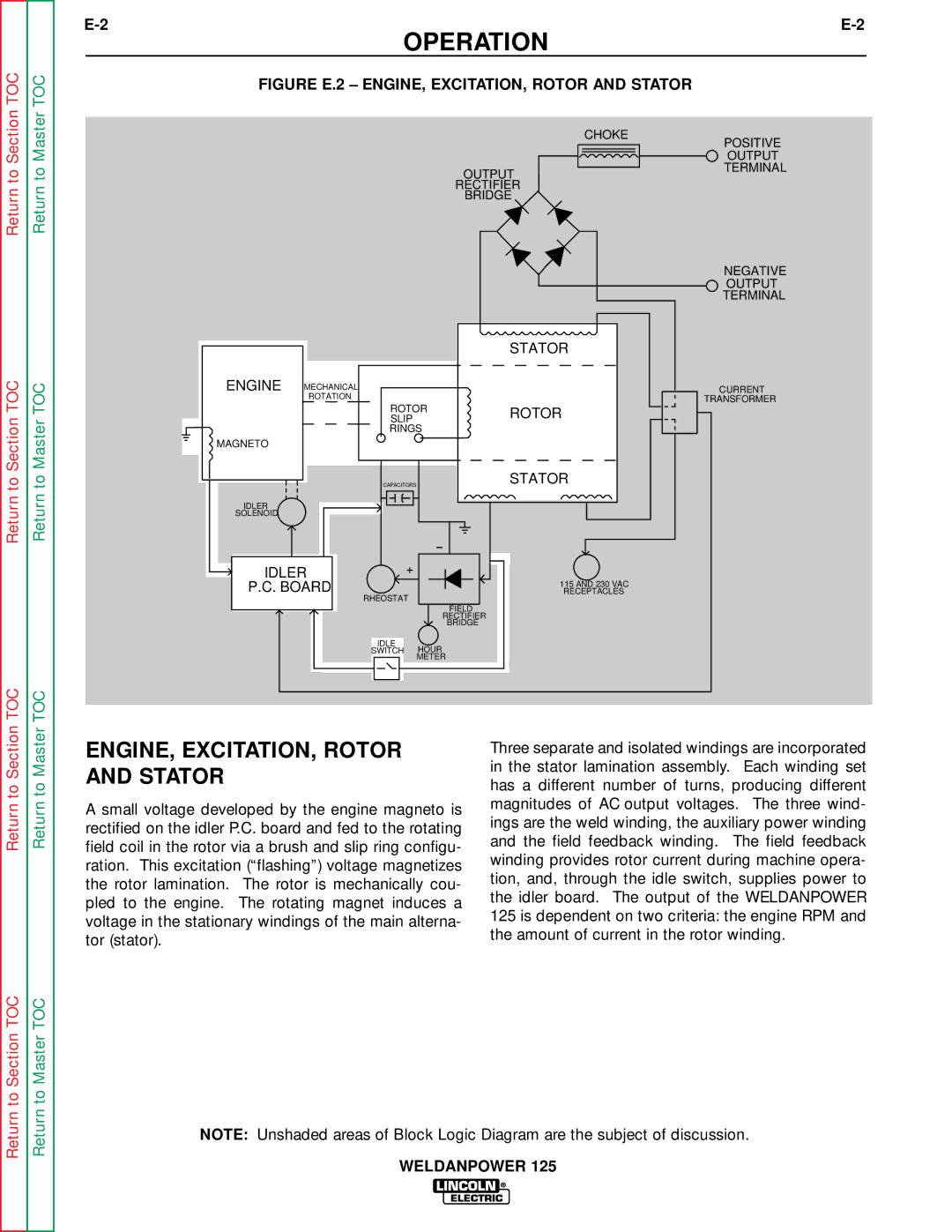
FIGURE E.2 – ENGINE, EXCITATION, ROTOR AND STATOR
| CHOKE |
| POSITIVE |
| OUTPUT |
OUTPUT | TERMINAL |
| |
RECTIFIER |
|
BRIDGE |
|
Return to Section TOC
Return to Master TOC
|
|
|
| STATOR |
ENGINE | MECHANICAL |
|
|
|
| ROTATION |
|
|
|
|
| ROTOR | ROTOR | |
|
| SLIP |
| |
|
| RINGS |
| |
MAGNETO |
|
|
|
|
|
| CAPACITORS |
| STATOR |
IDLER |
|
|
|
|
SOLENOID |
|
|
|
|
IDLER | + |
|
| |
P.C. BOARD |
|
| 115 AND 230 VAC | |
RHEOSTAT |
| RECEPTACLES | ||
|
|
|
| |
|
|
| FIELD |
|
|
|
| RECTIFIER |
|
|
|
| BRIDGE |
|
|
| IDLE | HOUR |
|
|
| SWITCH |
| |
|
|
| METER |
|
NEGATIVE OUTPUT TERMINAL
CURRENT
TRANSFORMER
Return to Section TOC
Return to Master TOC
ENGINE, EXCITATION, ROTOR AND STATOR
A small voltage developed by the engine magneto is rectified on the idler P.C. board and fed to the rotating field coil in the rotor via a brush and slip ring configu- ration. This excitation (“flashing”) voltage magnetizes the rotor lamination. The rotor is mechanically cou- pled to the engine. The rotating magnet induces a voltage in the stationary windings of the main alterna- tor (stator).
Three separate and isolated windings are incorporated in the stator lamination assembly. Each winding set has a different number of turns, producing different magnitudes of AC output voltages. The three wind- ings are the weld winding, the auxiliary power winding and the field feedback winding. The field feedback winding provides rotor current during machine opera- tion, and, through the idle switch, supplies power to the idler board. The output of the WELDANPOWER 125 is dependent on two criteria: the engine RPM and the amount of current in the rotor winding.
Return to Section TOC
Return to Master TOC
NOTE: Unshaded areas of Block Logic Diagram are the subject of discussion.
WELDANPOWER 125
