Return to Section TOC
Return to Section TOC
Return to Master TOC
Return to Master TOC
TROUBLESHOOTING & REPAIR
MAIN STATOR TEST (continued)
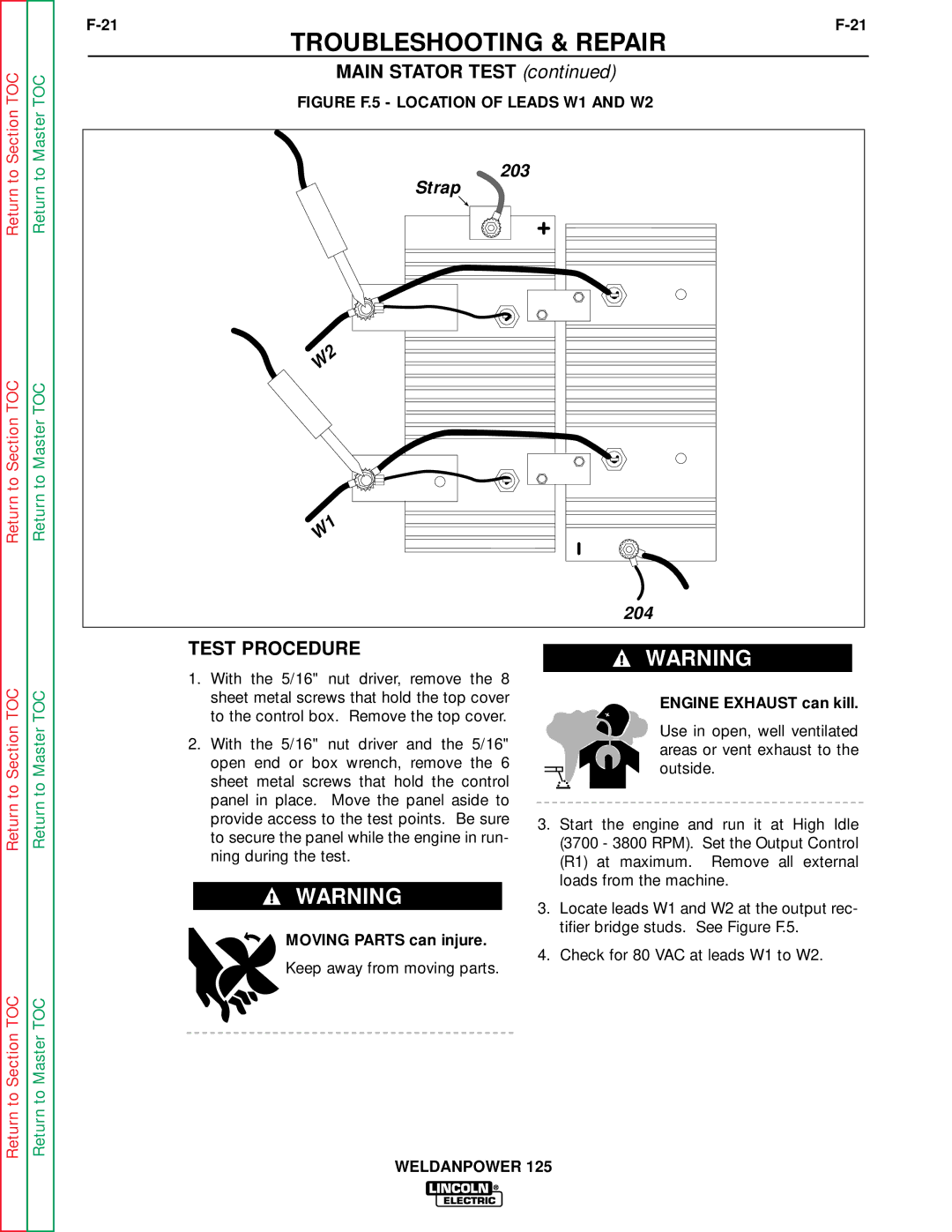
FIGURE F.5 - LOCATION OF LEADS W1 AND W2
203
Strap
W2
W1
204
Return to Section TOC
Return to Section TOC
Return to Master TOC
Return to Master TOC
TEST PROCEDURE
1.With the 5/16" nut driver, remove the 8 sheet metal screws that hold the top cover to the control box. Remove the top cover.
2.With the 5/16" nut driver and the 5/16" open end or box wrench, remove the 6 sheet metal screws that hold the control panel in place. Move the panel aside to provide access to the test points. Be sure to secure the panel while the engine in run- ning during the test.
![]() WARNING
WARNING
MOVING PARTS can injure.
Keep away from moving parts.
![]() WARNING
WARNING
ENGINE EXHAUST can kill.
Use in open, well ventilated areas or vent exhaust to the outside.
3.Start the engine and run it at High Idle (3700 - 3800 RPM). Set the Output Control (R1) at maximum. Remove all external loads from the machine.
3.Locate leads W1 and W2 at the output rec- tifier bridge studs. See Figure F.5.
4.Check for 80 VAC at leads W1 to W2.
WELDANPOWER 125